
The pressure surrounding the mechanical seal and its shaft sleeve imposes an axial force – a thrust – on the shaft. This thrust load and direction can be determined by summing the products of the various pressures and areas of the seal and sleeve. Fortunately, many of these products cancel each other out and the thrust load can be computed in a simple manner.
The method shown below for calculating thrust load is taken from Chapter 17, “Seal Thrust Loads on Pump Shafts”, of Mechanical Seals for Pumps: Application Guidelines from the Hydraulic Institute and Fluid Sealing Association. Only the thrust load for single pusher seals is shown in this post but the book includes dual seals and bellows seals.
The general idea is that there is a hydraulic area between the balance diameter of the seal and the shaft upon which the seal chamber pressure acts to produce an axial thrust. This hydraulic area is given by
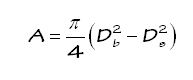
where
-
- A is the hydraulic “thrust” area, inch2
- Db is the balance diameter of the seal, inch
- Ds is the OD of the shaft, inch.
The thrust force is the product of the seal chamber pressure and thrust area.
The location of the balance diameter is illustrated below.
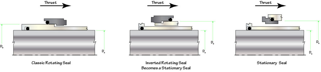
For many seals, the balance diameter can be estimated from the shaft size as follows:
- Classic rotating seal: shaft diameter plus 1/2” to 5/8”
- Inverted rotating seal (made into stationary seal): shaft diameter plus 5/8” to 1”
- Stationary seal: shaft diameter plus 5/8” to 1”.
These approximations to the balance diameter can be made because, typically, radial thicknesses, radial steps and even O-ring cross sections are based on 1/8” increments. Radial clearances are often based on 1/16”; seals with large radial clearances may also have larger balance diameters. Another variation comes from the shaft diameter not being an exact 1/8” increment and the sleeve may be used as an “adapter”. Of course, the exact balance diameter depends on the seal design, thicknesses, clearances, etc. and the seal manufacturer should be consulted.
So, how much thrust is produced by the seal? Sometimes, quite a lot – especially for large seals at high pressures. The graph below is based on a classic rotating seal with balance diameter 1/2” larger than the shaft and a stationary seal with balance diameter 3/4” larger than the shaft.
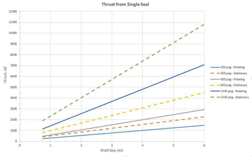
Obviously, the thrust load estimated here for a stationary seal exceeds that of a rotating seal but this may not always be the case. Again, the details of the seal design must be checked. However, it is often the case that the thrust load from a stationary seal is larger than that from a rotating seal; therefore, it is best to consider a stationary seal configuration when making general assumptions about thrust loads.
This thrust load is transmitted to the shaft – typically by set screws – but devices such as pins, slots, grooves, split rings, etc. are sometimes used. Therefore this thrust load is added to the thrust load imposed on the pump bearings. Note that if the pump uses two seals (one on the driven end and one on the non-driven end) then the net thrust load from the seals that is imposed on the bearings may be zero.
Eventually, this blog post will make its way into the design pages of SealFAQs. In a later post, we’ll take a look at the thrust capacity of set screws.