
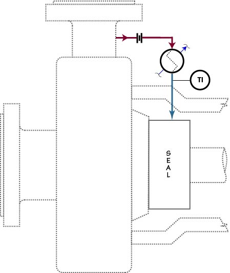
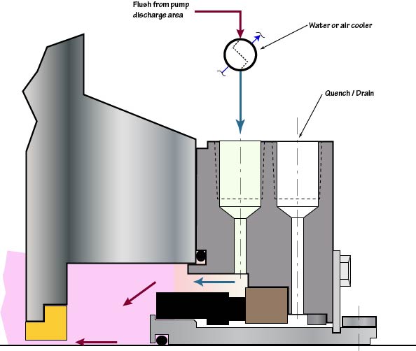
Plan 21 is a variation of Plan 11 that includes cooling. In Plan 21 the product flows from pump discharge through an orifice and then to a heat exchanger to reduce the temperature before being introduced into the seal chamber. The heat exchanger can be either water cooled or air cooled. A temperature indicator should be included on the process side of the exchanger, normally on the downstream side. Additional temperature indicators are used in some installations to monitor cooling water and process temperature on both sides of the exchanger. Note that it is not always necessary to cool the process fluid.
The flow rate should be controlled by an orifice located in the flush line. API standards show the orifice being located upstream of the exchanger. However, with process fluids that are near their vapor pressure, improved results can be realized by locating the orifice between the exchanger and the seal chamber.
On cooled piping plans it is helpful to include a close clearance, floating, throat bushing to isolate the cooled seal chamber from the hot pump. Such a bushing will also slightly increase the seal chamber pressure on Plan 21 and therefore further suppress vapor formation in the seal chamber.
A cooling piping plan, such as Plan 21, should never be used for the purpose of allowing the use of materials with lower high end temperature limits. The materials used, throughout the seal, should be designed to withstand the full range of process temperatures.
Plan 21 is not a preferred plan, either by the API or many users, because of the high heat load that is put on the heat exchanger in this plan. High heat load results in wasted energy and a high rate of fouling of the heat exchanger which often results in shortened seal life. Fouling normally occurs on the water side of cooling tower based cooling systems. This can be averted, to some degree, by maintaining a velocity sufficient to resist the deposit of cooling water sediment on the coils. On many systems this is difficult to do. It is highly recommended that a temperature indicator be installed in the process stream, on the downstream side of the heat exchanger to monitor the condition of the exchanger.