
This section is about details and specifics to 2nd and 3rd edition of API 682 that were not included in 1st Edition. Many of these details and specifics have carried through to 4th edition.
One of the major criticisms of API 682 1st Edition was that the seals were “heavy duty” and expensive with no alternative seal for easy services. To some degree, this was intentional and was done in order to reduce inventory, promote familiarity with a limited number of seal types and to increase reliability.
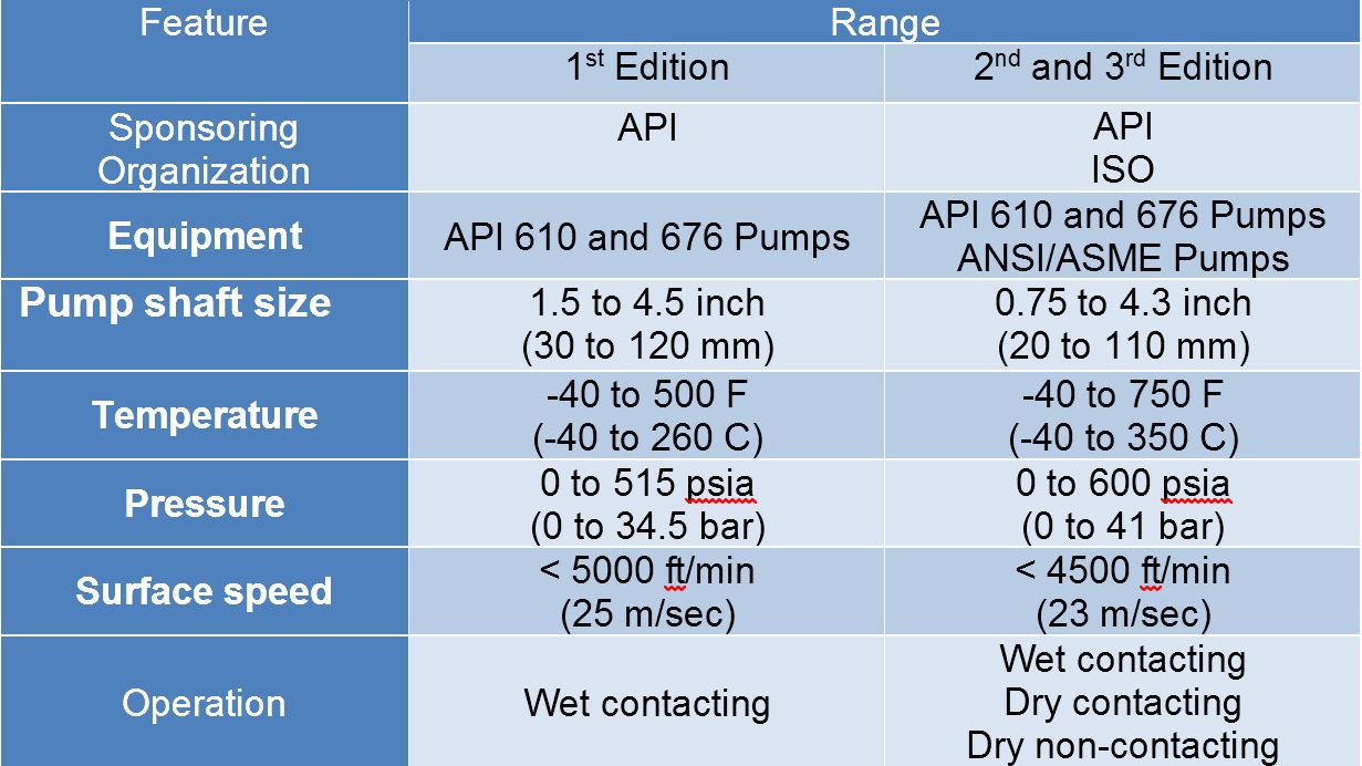
The first edition of API 682 was not particularly well accepted. Some criticized its lack of flexibility; others pointed out that it specified expensive “heavy duty” seals even for light duty services. In particular, designers and operators of chemical plants were upset because first edition did not deal with specifications for chemical duty pumps. At the time first edition was issued, sealing technology was evolving to include non-contacting seals but those designs were not considered in first edition. API 682, second edition addressed all these concerns.
The review process for API 682, first edition, resulted in a recommendation to write a second edition and a new taskforce was formed. Again, the taskforce consisted of users and manufacturers; however, this second edition taskforce was international and also included members from the chemical processing industries. Joseph M. Thorp, an Engineering Specialist within the Technical Services Department of Aramco Services Company, was named chairman of the API 682 committee and taskforce and meetings began in late 1998. Over the next four years, the membership of the taskforce ranged from 15 to 20 people including three from the original taskforce: Ken Lavelle, Rick Eickhoff and Gordon Buck.
As it turns out, most seals sold to the Hydrocarbon Processing Industries since API 682 1st Edition was issued were not true API 682 seals. There were three primary reasons for the modest sales of true API 682 seals: initial cost, end user procedures and long product life cycles. True API 682 seals will always have a higher initial cost than general purpose seals and there may be additional costs associated with inventory changes, pump modifications and sealing systems. Also, many end users seemed unsure of the applicability of the specification and/or reluctant to take on their own internal policies and purchasing standards in order to retrofit API 682 seals to existing pumps. Finally, in spite of the criticisms that led to the development of API 682, mechanical seals can be very reliable and therefore can have a very long product life cycle. With these thoughts in mind, the end user turned to seals “in the spirit of” API 682.
Although there is no real definition for “in the spirit of” API 682 seals, the general idea followed the major concepts, used premium materials and took advantage of the development of the true API 682 product. This can actually a good practice, especially when older, often nonconforming, pumps are to be retrofitted with improved mechanical seals rather than simply repairing existing older designs. The preference for “in the spirit of” was especially prevalent when 1st Edition of API 682 was the governing version.
After the release of API 682 1st Edition, gas seals and dry running containment seals became more common. New piping plans for gas seal control panels and containment seals were necessarily required and developed. In addition, many users and manufacturers wanted to expand the scope of seal configurations and orientations that had been specified by 1st Edition.
Another criticism of API 682 1st Edition was that it considered only API 610 pumps and only refinery applications. The chemical and petrochemical industries routinely use ASME pumps in addition to API 610 pumps. Broadening the scope of pumps covered by API 682 would allow standardized seals to be applied in a greater number of industries.
Although much of first edition lives on in the second edition, there are some major differences. For example, second edition recognizes the need for chemical duty seals and pumps not in compliance with API 610; this is accomplished through the definition of categories for seals. Second edition also includes both pressurized and unpressurized dry running seal arrangements as well as new piping plans for controlling them. New testing procedures were written for these dry running seals. First edition was criticized because it did not have a “pass – fail” criteria for the qualification tests but second edition does. At the same time, second edition is more flexible in that it allows more variety in seal orientation. Whereas all first edition dual seals were oriented face-to-back, second edition allows face-to-face or back-to-back orientation.
In 2nd Edition, the organization of API 682 was changed to conform to ISO standards:
- 1 – Scope
- 2 – Normative references
- 3 – Terms, Definitions, and Symbols
- 4 – Variations of Mechanical Seals
- 5 – General
- 6 – Design Requirements
- 7 – Specific Seal Configurations
- 8 – Accessories
- 9 – Instrumentation
- 10 – Inspection, Testing, and Preparation for Shipmen
- 11 – Data Transfer
- Annexes
- Annex A – Recommended Seal Selection Procedure
- Annex B – Typical Materials and Material Specifications
- Annex C – Mechanical Seals Datasheets
- Annex D – Seal Codes
- Annex E – Mechanical Seals Data Requirement Forms
- Annex F – Technical Tutorials and Illustrative Calculations
- Annex G – Standard Piping Plans and Auxiliary Hardware
- Annex H – Inspectors’ Checklist for All Seals
- Annex I – Seal Qualification Testing
This reorganization means that there is no simple cross reference guide between 1st edition and 2nd edition paragraphs numbers.
Whereas API standards used the terms “section” and “paragraph”, ISO standards use the term “clause”. However, it seems more descriptive to use “section” as the major division and “clause” for the detail.
Here’s a quick comparison of 1st and 2nd editions:
Categories
The second edition introduced the concept of seal categories. A seal category describes the type of pump into which the seal will be installed, the operating window, the design features, and the testing and documentation requirements. There are three categories designated as Category 1, 2, or 3.
Category 1 seals are intended for non-API-610 (ISO 13709) pumps. These will generally be applied into ASME B-73 big bore or ISO 3069 type C seal chambers. This category is applicable for temperatures between –40°F and 500°F (-40°C and 260°C) and pressures to 315 PSI (22 bar). The seal will be provided with minimal documentation and qualification testing is limited.
Category 2 seal are intended for API-610 (ISO 13709) pumps. This category is applicable for temperatures between –40°F and 750°F (-40°C and 400°C) and pressures to 615 PSI (42 bar). The seal will be provided with minimal documentation and qualification testing is limited.
Category 3 seals are also intended for API-610 (ISO 13709) pumps. These seals will be provided for the most demanding applications. This category is applicable for temperatures between –40°F and 750°F (-40°C and 400°C) and pressures to 615 PSI (42 bar). Design features include a distributed flush and floating throttle bushing for single seals. This seal must have been qualified according to the qualification test procedures. Additional documentation must be also provided.
New seal types
Three new seal types have been introduced in the second edition: dry running containment seals, non-contacting seals, and dual gas barrier seals.
Containment seals are the outer seal in a dual unpressurized seal arrangement. In the second edition, containment seals can be used with a liquid buffer fluid, a gas buffer fluid or without a buffer fluid. In the case of a dry running containment seal, the containment seal will be exposed primarily to buffer gas or vaporized process fluid. Such containment seals must therefore be designed for continuous dry running while meeting the reliability goals of the standard. Dry running containment seals may be either contacting or non-contacting.
Non-contacting inner seals are also introduced in this edition. A non-contacting inner seal is designed to operate on liquid, vapor, or mixed phase fluids. One of the primary targets for non-contacting inner seals is in flashing hydrocarbon services. In some of these services, it is impossible to obtain adequate vapor margins to prevent flashing of the fluid in the seal chamber. A non-contacting seal is designed for lift-off on vapor phase fluids. If the seal is exposed to liquid phase fluids, it will also lift-off and continue to run though the leakage past the seal will be higher. This seal will be used with a dry running containment seal and the leakage past the inner seal will be piped to a vapor recovery system.
The other new seal type is the dry running gas seal used in dual pressurized arrangements. This seal is designed to run primarily on a gas barrier fluid such as nitrogen.
Arrangements
The seal arrangement describes the number of seals per cartridge, the orientations of dual seals, and the relative pressure of the buffer/barrier fluid. A chart of available arrangements is shown in Figure 1. Where multiple arrangements are listed in a column, they are shown in order of preference. The arrangements are described by an arrangement code shown in the figure.
Arrangement 1 seals are defined as a seal configuration having one seal per cartridge assembly. These are also commonly called single seals. Arrangement 1 seals are available with a fixed throttle bushing (1CW-FX) or a floating throttle bushing (1CW-FL).
Arrangement 2 seals are defined as a seal configuration having two seals per cartridge assembly with a containment seal chamber that is at a pressure less than the seal chamber pressure. Arrangement 2 seals can be used with a liquid buffer fluid (2CW-CW) or with a dry running containment seal (2CW-CS). The dry running containment seal may be either a contacting or non-contacting (lift-off) seal. In addition, there has been some success in using a non-contacting inner seal with a dry running containment seal (2NC-CS) in services such as flashing hydrocarbons.
Arrangement 3 seals are defined as a seal configuration having two seals per cartridge assembly that utilize an externally supplied barrier fluid. By definition, the barrier fluid is at a pressure higher than the seal chamber pressure. Arrangement 3 seals can be used with either a liquid or gas barrier fluid. These seal can also be configured with the seals in a face-to-back, face-to-face, or back-to-back orientation.
New piping plans
Several new piping plans have been introduced in the second edition. These include additional options for dual pressurized liquid seals as well as new piping plans to support containment seals and dual pressurized gas seals.
Plan 14. This plan is a combination of Plan 11 and Plan 13. This was introduced in API-610 8th edition and is now included in API-682. This plan is primarily used in vertical pumps to allow for injection into the seal chamber while continually venting the seal chamber back to suction. (Figure 2)
Plan 53. This plan is used to provide pressurized barrier fluid to Arrangement 3 seals. In the first edition, this was shown as a pressurized reservoir. While this style of Plan 53 is commonly used, other variations do exist. These variations have not had an official designation but have assumed names like “Plan 53 Modified”. The second edition has defined three variations of Plan 53 and uses the designations Plan 53A, Plan 53B, and Plan 53C. If the user wishes to specify a specific variation, they can use these designations. If the user does not specify a specific variation and uses the term Plan 53, any of the variations are considered acceptable.
Plan 53A. This plan is the same as Plan 53 in the first edition of API 682. An externally supplied gas such as nitrogen pressurizes a barrier fluid reservoir. Barrier fluid is pumped from the seal to the reservoir by a pumping device on the seal and flows back to the seal by gravity. An advantage of this system is that cooling coils can be provided in the reservoir. Combined with the large volume of fluid in the circulation system, fluid conditions remain very stable. Barrier fluid pressure can also be controlled very accurately with a pressure regulator on the nitrogen line. The disadvantage of this system is that, at high pressures, the pressurization gas can dissolve into the barrier fluid. This may cause instability in the seals. (Figure 3)
Plan 53B. This plan uses a small closed loop without a reservoir. Barrier fluid is pumped into the loop by a pumping device and is circulated back to the seal. In most cases a seal cooler (either air-cooled or water-cooled) is placed in the loop to control the barrier fluid temperature. A bladder accumulator that is connected to the loop pressurizes the barrier fluid. The accumulator serves the dual role of providing make-up fluid and pressurization to the loop. This accumulator is pressurized so leakage from the loop does not drop the barrier fluid pressure below the seal chamber pressure. The advantage of this system is that it can be used at high pressure without pressurization gases dissolving into the barrier fluid. It is also common to use this system in areas where cooling water is not available and air-cooled seal coolers must be used. The disadvantage is that the accumulator must be sized adequately to prevent large pressure fluctuations due to seal leakage and an external seal cooler must be provided. These can make this variation more expensive than Plan 53A. (Figure 4)
Plan 53C. This plan also uses a small closed loop without a reservoir. Barrier fluid is pumped into the loop by a pumping device and is circulated back to the seal. A piston accumulator that is connected to the loop pressurizes the barrier fluid. The accumulator serves the dual role of providing make-up fluid and pressurization to the loop. The piston accumulator is designed to take a reference pressure line (generally off of the seal chamber) and provide a higher pressure into the barrier fluid loop. Because of the design of the accumulator, the pressurization of the loop is at some constant ratio over the reference pressure (e.g. 1:1.15). The advantage of this system is that the pump pressurizes the loop and no external gas supply is required. The system automatically tracks the pressure in the seal chamber to compensate for variations in pump operating conditions. The system can be operated at high pressures without dissolving pressurization gas into barrier fluid. A disadvantages is that the piston accumulator is exposed to pump fluid. It is therefore exposed to corrosion and contamination from the pump process. It is also generally more expensive than a Plan 53A. (Figure 5)
Plan 71. This plan is designed for dry running containment seals. Ports are provided for buffer gas but are plugged during installation. This plan is used when barrier gas may be required in the future. (Figure 6)
Plan 72. This plan is designed for dry running containment seals (2CW-CS and 2NC-CS). A buffer gas is supplied to the containment seal chamber to sweep leakage from the seal to a collection system. The buffer gas pressure is lower than seal chamber pressure. The plan describes a control panel to filter the buffer gas, regulate the pressure, and provide instrumentation to monitor operation. (Figure 7)
Plan 74. This plan is designed for dual pressurized gas seals (3NC-FB, 3NC-BB, and 3NC-FF). A barrier gas is supplied at a pressure higher than seal chamber pressure. The plan describes a control panel to filter the barrier gas, regulate the pressure, and provide instrumentation to monitor operation. (Figure 8)
Plan 75. This plan is used for dry running containment seals (2CW-CS and 2NC-CS). This plan is designed for applications where leakage past the primary seal does not completely vaporize. Leakage is piped from the containment seal chamber to collection chamber where liquid and gas phases of the leakage are separated. (Figure 9)
Plan 76. This plan is used for dry running containment seals (2CW-CS and 2NC-CS). This plan is designed for applications where the leakage past the primary seal completely vaporizes. Vapors are collected and piped to a vapor recovery system. (Figure 10)
New Qualification Procedures
One of the strengths of the first edition was to provide qualification tests where seal vendors would be required to prove the suitability of the their seals for a given service. The second edition expands on these requirements by adding new tests for containment seals and dual gas seals as well as defining acceptance criteria for all tests.
Containment seals operate under low pressure, dry running conditions for the majority of their life. They are primarily intended to contain process fluid in case of failure of the inner seal. The testing of a containment seal is designed to simulate such a failure. First, a seal cartridge (consisting of a liquid inner seal and dry running containment seal) is subjected to the standard seal qualification test. The standard seal qualification test includes a 100 hour dynamic phase, a four hour static phase, and number of pressure and on/off cycles. During this portion of the test, the containment seal is seeing only normal leakage past the inner seal. Afterward, the containment seal will be operated for 100 hours on propane at 10 PSI (0,7 bar) at 3600 RPM. The seal will be stopped, pressurized to 25 PSI (1,8 bar), blocked in, and held for five minutes. The containment seal chamber will then be filled with diesel at 40 PSI (2,8 bar) and operated at 3600 RPM for an additional 100 hours. The seal will again be stopped and maintained at 250 PSI (17,2 bar) for four hours. Results of leakage will be taken at specified points during the test. (Figure 11)
Dual pressurized gas seals will first be tested to the standard seal qualification test. After this, the seal will be tested for loss of barrier gas pressure. The seal will be stopped and the barrier gas pressure will be reduced to 0 PSI for one hour. The barrier gas will be reapplied and the seal operated until the system reaches equilibrium. The barrier pressure will then be reduced to 0 PSI for one minute and then the pressure reapplied. This will simulate a gas barrier pressure loss in operation. The seal will then be stopped and blocked in for 10 minutes. Results will be recorded at specified points during the test. (Figure 12)
Category 3 seals must be tested in the same configuration, type, design, and materials as the commercially available seal design. Category 1 and 2 seals must also be tested. However, if Category 1 and 2 seals are constructed of seal faces that are used in a previously qualified Category 3 seal, no further testing is required. The maximum allowable leakage during testing is 1000 ppm (vol) vapors (as measured by EPA Method 21) or 5.6 g/h liquid leakage per pair of sealing faces. The maximum allowable face wear at the completion of the testing must be less than 1% of the available seal wear length.
New seal selection procedure
The seal selection procedure provides the user with a standard methodology for selecting a seal for a variety of refinery and general services. Although chemical and petrochemical industries are now covered by API-682, the selection procedure did not attempt to cover every application due to the myriad of process fluids involved in these industries. The procedure is a series of steps that directs the user to collect information on the application, regulations, and local requirements. This information is used to select the seal category, type, arrangement, and piping plan. A flowchart that describes the sequence of steps is shown on Annex A. (Figure 13)
Seal category
The first step in selecting a seal is to determine the seal category required for the service. The category is a function of the pump design, the operating conditions, the design features of the seal, and the documentation required by the user. A comparison of the seal categories is shown in Annex A of the standard.
Seal type
Applications are divided into three major services: non-flashing hydrocarbon, flashing hydrocarbon, and non-hydrocarbon. Non-hydrocarbon services are further divided into water, sour water, caustic, amines, crystallizing services and acids. Each of the service groups is defined for a range of pressure of temperatures. The applicable seal types are listed under each of the groups along with any special design or material recommendations for the specific service.
Seal arrangement
Selection of the seal arrangement is a function of regulations, hazard assessment, and process fluid properties. All applications start with an Arrangement 1 (single seal). The user follows a flowchart of “yes or no” questions until they reach the end of the chart. At this point, the final arrangement (1, 2, or 3) is determined.
Seal flush and quench
The selection flowcharts for piping plans are divided into the same three services as the seal type selection: non-flashing hydrocarbon, flashing hydrocarbon, and non-hydrocarbon. Each of these flowcharts has a starting point for each of the arrangements. The user answers a number of questions about the process conditions, fluid properties, and the presence of contaminants. The user then follows the flowchart to arrive at the suggested piping plan for the seal flush and quench.
Barrier fluid
Selection of a barrier or buffer fluid is critical to the success of liquid ual seals. Barrier and buffer fluids must be compatible with the process fluid and seal materials of construction. In addition, it must provide adequate lubrication for the seals and have suitable fluid properties over the entire range of expected operating conditions. Guidelines for barrier/buffer fluid selection are given in the Annex A of the standard.