
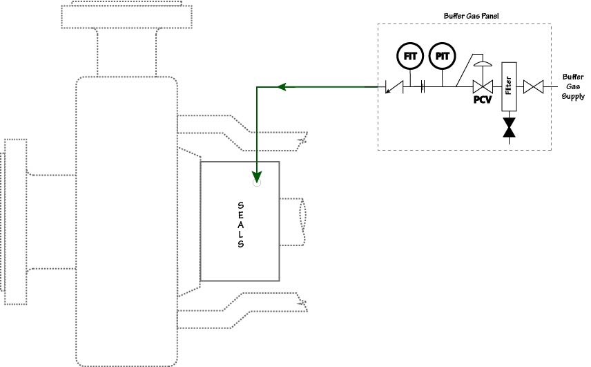
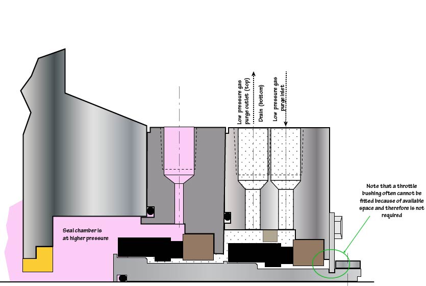
Plan 72 uses an external low pressure buffer or purge gas, usually nitrogen, which is regulated by a control panel and then injected into the outer seal cavity. The control panel may contain a pressure control valve to limit buffer gas pressure to prevent reverse pressure on the inner seal and/or limit pressure applied to the secondary containment seal followed by either an orifice or needle valve to control the gas flow rate. The control panel may also have a coalescing filter to prevent solids and/or liquids within the buffer gas from contaminating the secondary containment seal. A very important feature of Plan 72 is that the gas purge is introduced close to the seal faces whereas the vent and drain are away from the seal faces. In API 682 a bushing is required in the containment chamber to physically separate the buffer inlet and the vent/drain.
Note that the flow rate and regulation of the buffer or purge gas is accomplished by Plan 72 and not by Plan 75 or 76.
Plan 72 would ordinarily be used in conjunction with Plan 75 for primary seal leakage that is condensing or Plan 76 for non-condensing leakage to help minimize process fluid affecting the containment seal faces and dilute leakage to the atmosphere. Plan 72 should not be used in a dead-ended containment chamber.