
It probably seems strange to consider the pump as auxiliary equipment for the seal ……..
Some seal systems do indeed include pumps but this page is actually about the pump which houses the seal.
Seal Chamber Dimensions
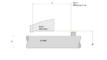
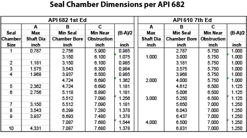
Since the seal chamber is considered to be part of the pump, the dimensions are set by and included in the pump standard API 610. However, those dimensions were first developed by the API 682 1st Edition Task Force and published in API 682 1st Edition. This was not pleasing to the API 610 Committee and subsequent editions of API 682 do not address or include pump dimensions. API 682 seals are intended to be used in the seal chamber dimensional envelope shown below.
Centrifugal Pump Failures
One way of looking at pump failures is to group them according to the design, application, operation or repair functions. Since we are considering these functions as part of the “big picture”, we will group pump failures according to the major hardware component which failed. Doing so allows us to learn about the components used in centrifugal pumps. As a sort of gross average, the table below shows a range of typical failure distribution.
Causes of Pump Failures
- Mechanical seal 60 to 70%
- Bearings 15 to 25%
- Pumping rate 5 to 10%
- Miscellaneous 5 to 15%.
Estimating the Pressure in Pump Seal Chambers
The pressure in the pump stuffing box must be known before the proper seal and flush system can be selected. For some pumps, the stuffing box pressure is the same as the pump suction pressure; for others, it may be near discharge pressure. The exact value depends on the fluid, flowrate, design and condition of the pump. Often, accurate information is not available even from the pump manufacturer; it is always best to measure the stuffing box pressure. This procedure shows how to estimate the stuffing box pressure when measured data is not available.
Single Stage, Single Suction, Overhung Process Pumps
Overhung process pumps are by far the most common type of pump used in the process industries. These pumps can be either horizontal or vertical (inline). The stuffing box is located near the back of the impeller and the stuffing box pressure can be estimated as
where Pb is the pressure in the stuffing box
Ps is the pump suction pressure
Pd is the pump discharge pressure.
Balance holes/back wear rings. Many overhung process pumps use balance holes and back wear rings in the impeller to decrease the thrust load on the bearings. These features also set the stuffing box pressure. The pressure is a function of the shaft speed, impeller size, wear ring size and clearance, balance hole size and location, and fluid properties. In Equation 1, use C= .2 if the impeller is maximum size but use C = .1 for minimum size impeller if the wear ring clearance is less than twice the recommended values of API 610.
Without balance holes. Balance holes may not be needed to reduce the thrust load, especially at higher suction pressures. For these pump designs, the stuffing box pressure is very close to discharge pressure; use C = 1 in Equation 1 (this estimates the stuffing box pressure as discharge pressure).
Pump-out vanes. Some pumps use pump-out vanes instead of balance holes to reduce thrust. This is especially popular on ANSI pumps. Impeller clearance from back plate is critical to the efficiency of these pump-out vanes. The stuffing box is slightly above suction pressure. Trimming the impeller also trims the pump-out vanes. In Equation 1, use C = 0.3 if the impeller is at minimum diameter but C=.1 if the impeller is at maximum diameter.
Example
A single stage, single suction pump that uses balance holes and back wear rings has a suction pressure of 10 psig and a discharge pressure of 200 psig. What is the stuffing box pressure when the impeller is mid-sized?
Use Equation 1. For an impeller midway between maximum and minimum diameters, use C = .15, then
Single Stage, Double Suction Pumps
Double suction impellers can be provided for many different pump constructions including single stage overhung, single stage between bearings, horizontal multistage and vertical multistage. Next to the single stage, single suction, overhung construction, the next most common pump construction is probably the single stage, double suction impeller placed between bearings. This design requires a mechanical seal on each side of the impeller. The stuffing boxes are placed next to the impeller suction eye; therefore stuffing box pressure is the same as suction pressure.
Multistage Pumps
Multistage pumps can be mounted horizontally or vertically. They might use single or double suction impellers. Balance holes, wear rings, balance drums, balance lines, orifices, impeller orientation and many other features are used to control thrust and stuffing box pressure.
Two stage horizontal pumps. There are two distinct types of two stage horizontal pumps. Each has two stuffing boxes. One design has the impellers “back to back” with the stuffing boxes located near the impeller suction eyes. Therefore one stuffing box is at pump suction pressure per Equation (2). The other stuffing box is at second stage suction (first stage discharge) which is midway between suction and discharge pressures, so, for this high pressure stuffing box use
Another design has the impellers “eye to eye”. The stuffing boxes are located near the back of the impeller. This means that one stuffing box is at the discharge pressure of the first stage, see Equation (3). The other stuffing box is at the discharge pressure of the second stage (pump discharge pressure).
If a balance line is used, use the method described for multistage pumps with balance lines.
Example
A two stage pump with impellers placed “eye to eye” has a suction pressure of 10 psig and a discharge pressure of 400 psig. What is the estimated stuffing box pressure?
The low pressure box is at (using Equation 3)
The high pressure box is at pump discharge pressure, 400 psig.
Multistage horizontal pumps with balance lines. Multistage impellers are used to develop high pressures, but the stuffing box is not necessarily at a high pressure. Most horizontal multistage pumps with opposed impellers (boiler feedwater, pipeline) have two stuffing boxes: a “low pressure” box at suction pressure and a “high pressure” box at a pressure between suction and discharge. A balance line connecting the stuffing box to the pump suction chamber is used to reduce the pressure in the high pressure stuffing box. When the pump is in good repair, the high pressure stuffing box is around
For multistage pumps with opposed impellers, if the balance line is not used or if the close clearance throat bushing is not maintained, then the pressure in the high pressure stuffing box approaches midway between suction and discharge pressure per Equation (3).
Example
A multistage pipeline pump has a suction pressure of 350 psig and a discharge pressure of 1200 psig. What is the estimated stuffing box pressure? What would the pressure be if the balance line were not used?
The low pressure box is at pump suction pressure, 350 psig.
For the high pressure box, per Equation (4)
Without the effects of the balance line, using Equation (3), the high pressure box can reach
Multistage vertical can (turbine) pumps. In these pumps even though the individual impellers may have balance holes and back wear rings, the stuffing box is located in the discharge nozzle. Therefore, the stuffing box pressure would be at pump discharge pressure except for the effects of a balance, or bleed-off, line. When the pump is in good repair, the stuffing box can be estimated using Equation (4).
Example
A multistage vertical can pump has a suction pressure of 350 psig and a discharge pressure of 1200 psig. What is the estimated stuffing box pressure? What would the pressure be if the balance line were not used?
With the balance line, using Equation (4)
Without the effects of the balance line, the box can reach pump discharge pressure, 1200 psig.