
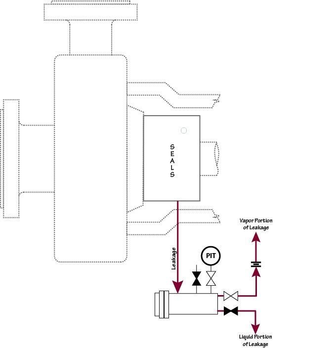
Plan 75 is intended for use when the leakage will be mostly in a liquid form. In this arrangement the drain is located at the bottom of the outer seal gland and is routed to a reservoir. Liquid leakage is collected and the gaseous portion is further routed through an orifice to a flare or vapor recovery system. The reservoir does contain a pressure gage and a high pressure switch to indicate a buildup in pressure in the reservoir from excessive primary seal gaseous leakage or a primary seal failure of some magnitude. A level switch to warn of excessive liquid leakage is optional on the reservoir.