
A seal code is an abbreviated method of communicating basic specifications for the mechanical seal. Sadly, the seal code has been changed with every edition of API 682. Fortunately, the new code, described in API 682 4th Edition Annex D, is the best to date and includes some concepts and codes from the historical API 610 seal code. The new code uses eight fields:
- Seal category
- Seal arrangement
- Seal type
- Containment device
- Gasket material
- Face material
- Approximate shaft size (in millimeters)
- Piping plan
API 682 4th Edition was the first edition to include materials in the description and in many ways represents a combination of API 682 coding and the old API 610 codes.
API 682 4th Edition Codes
4th Edition coding comprises four sections, some being sub-divided. The table below shows the construction of a typical seal code, it is intended to accurately describe the seal and seal system being implemented in a given application.
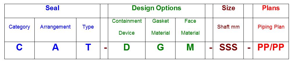
Code details are as follows:
- C: Category 1, 2 or 3 per API 682 4th Edition definitions
- A: Arrangement 1, 2 or 3 per API 682 4th Edition definitions
- T: Seal type A, B or C per API 682 4th Edition definitions. For dual seals using different inner and outer seal types, show both types using the format inner/outer.
- D: Containment device
- P = plain gland with no bushing
- L = floating throttle bushing
- F = fixed throttle bushing
- C = containment seal
- S = floating, segmented carbon bushing
- X = unspecified, not included in codes
- G: Gasket material. For dual seals using different inner and outer gasket materials, show both types using the format inner/outer.
- F = FKM
- G = PTFE
- H = Nitrile
- I = FFKM
- R = flexible graphite
- X = unspecified, not included in codes
- M: Seal face material. For dual seals using different inner and outer face materials, show both types using the format inner/outer.
- M = carbon vs nickel bound tungsten carbide
- N = carbon vs reaction bonded silicon carbide
- O = reaction bonded silicon carbide vs nickel bound tungsten carbide
- P = reaction bonded silicon carbide vs reaction bonded silicon carbide
- Q = sintered silicon carbide vs sintered silicon carbide
- R = carbon vs sintered silicon carbide
- S = graphite loaded, reaction bonded silicon carbide vs reaction bonded silicon carbide
- T = graphite loaded, sintered silicon carbide vs sintered silicon carbide
- X = unspecified, not included in codes
- SSS: Shaft size in mm; not necessarily a precise value
- PP/PP: Piping plan number(s) from API 682 4th Edition Annex G
Note that the codes used for Design Options are the same as those used in API 610 for materials that are included in both systems. On the other hand, some materials cannot be specified because API 682 does not recommend them. Such materials must be specified with an “X”.
All “X” codes must be explained in notes or the seal data sheet.
Show the piping plans in numerical order. There may be one, two, three or even more piping plans being used.
Examples of API 682 4th Edition Seal Codes
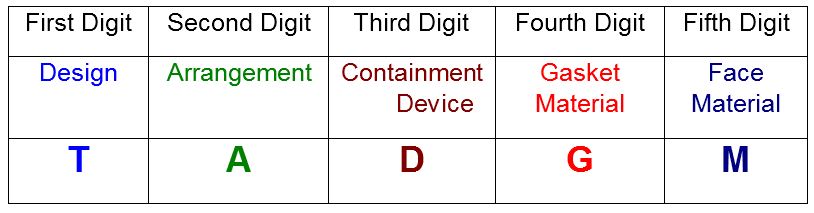
21A-LFN-060-11
2 – Category 2
1 – Arrangement 1
A – Type A (pusher) seal
L – Floating bushing
F – Fluoroelastomer secondary seals
N – Carbon vs reaction bonded silicon carbide
060 – 60 mm shaft size
11 – Piping Plan 11
33B-PIP/N-051-11/53A
3 – Category 3
3 – Arrangement 3
B – Type B (bellows) seal
P – Plain gland
I – Perfluoroelastomer (FFKM) secondary seals
P – Reaction bonded silicon carbide vs reaction bonded silicon carbide
N – Carbon v reaction bonded silicon carbide
051 – 51 mm (2” = 50.8 mm) shaft size
11 – Piping Plan 11
53A – Piping Plan 53A
API 610 Historical Seal Code
For many years the pump standard API 610 contained a mechanical seal coding system which became widely used in industry. This coding method provided a reference to the nomenclature and features used with mechanical seals that were current during that time period. While this coding method is obsolete it still is still being used in some areas of industry. It is presented herein as a historical reference only.
Codes details are as follows:
- T: Seal design type
- U = unbalanced seal
- B = balanced seal
- A: Seal arrangement
- S = single seal
- T = tandem seal
- D = double seal
- D: Containment device in gland plate
- P = plain gland with no bushing
- A = auxiliary sealing device
- T = throttle bushing
- G: Gasket material
- E = FKM/PTFE
- F = FKM
- G = PTFE
- H = Nitrile
- I = FFKM
- R = flexible graphite
- X = unspecified, not included in codes
- M: Seal face material
- J = carbon vs Stellite
- K = carbon vs Ni-resist
- L = carbon vs cobalt bound tungsten carbide
- M = carbon vs nickel bound tungsten carbide
- N = carbon vs reaction bonded silicon carbide
- O = reaction bonded silicon carbide vs nickel bound tungsten carbide
- P = reaction bonded silicon carbide vs reaction bonded silicon carbide
- X = unspecified, not included in codes
Example of API 610 Seal Code
A very commonly used code was BSTFM which translates to a balanced single seal with throttle bushing in the gland plate. Gaskets would be FKM (fluoroelastomer). Seal faces would be carbon vs nickel bound tungsten carbide.