
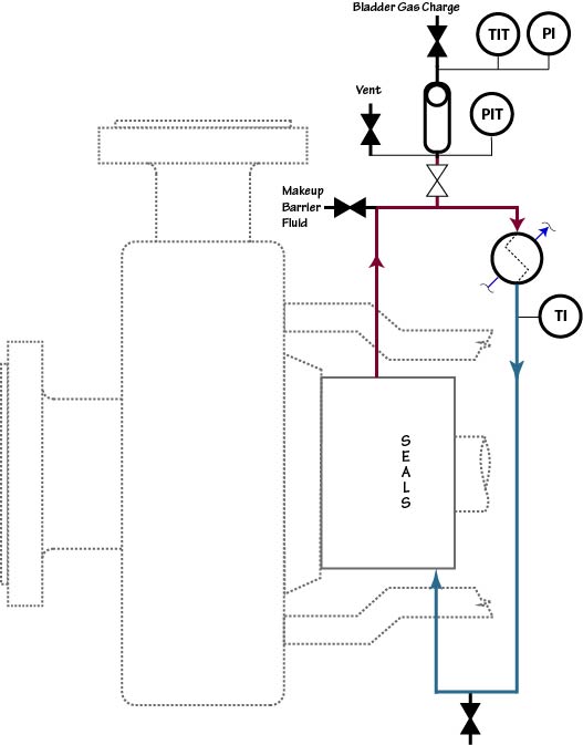
Unlike Plan 53A that incorporates a pressurized reservoir within the circulation loop, Plan 53B has only piping and an air or water cooled heat exchanger within the closed loop circuit. Liquid replenishment to this circuit is provided by a pre-pressurized bladder accumulator. The basic setup is comprised of two parts: the closed loop circulating system and the bladder accumulator. Seal performance is monitored by pressure decrease and not by barrier liquid volume as in Plan 53A. Flow in the circulating system is induced by an internal pumping device. The flow in this plan can only be achieved with proper exclusion of all gas and air bubbles from the heat exchanger and piping. Proper venting of the system during commissioning is crucial to successful system operation.
The circulation rate in a Plan 53B system is usually not controlled directly; it depends on the performance of the pumping ring within the particular closed loop system. The pumping ring, reservoir and piping are selected to produce the desired operating conditions. Heat soak as well as heat generation must be considered in determining the desired circulation rate.
It is important to realize that Plan 53A and 53B systems are operated differently and at different pressures. In Plan 53A, the barrier fluid pressure is nearly constant but in Plan 53B the barrier fluid pressure could vary over a wide range. In fact, in many ways, Plan 53B is more like Plan 23 than Plan 53A.
Although the concept of Plan 53B as described in API 682 is based on a refill interval of 28 days (and therefore a wide operating pressure range), some variations of Plan 53B are designed to have a smaller operating pressure range and therefore require frequent refill. For such 53B systems, the make-up system is usually large and permanently attached to the 53B. These “53B” systems may appear to be essentially a Plan 54 system and may be roughly the same cost.