
Although mechanical seals are used in all sorts of dirty fluids, it is well established that reliability is best when the fluid is clean. Therefore, there is a great incentive to provide a clean fluid flush for seals in dirty services. Piping Plan 31 is intended to clean up a dirty fluid to provide a clean flush to the seals. Frankly, I don’t particularly care for Plan 31 and have rarely used or recommended it.
Plan 31 relies on a “cyclone separator”, sometimes called an “abrasive separator”, or “hydrocyclone” to remove the dirt from the process fluid. I’ve always preferred the term “cyclone separator” because it gives me a mental image of how the separation works.
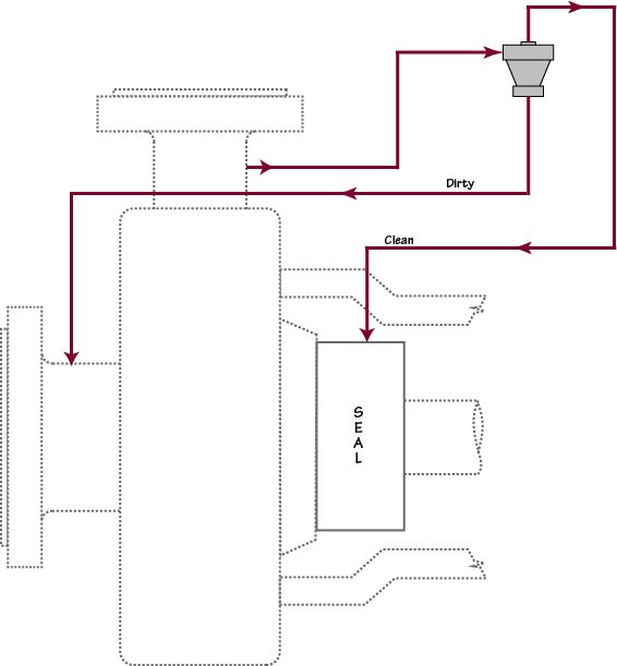
Plan 31 is a variation of Plan 11 in which a cyclone separator is added to the flush line. In Plan 31 the product, containing heavy, solid abrasives, is directed to the cyclone separator from the discharge of the pump. The cyclone separator uses centrifugal forces to concentrate the solids into one stream and therefore produces a clean stream as well. The clean fluid is routed out the top of the separator and into the seal chamber. The stream having concentrated heavy solids is routed back to pump suction. Roughly speaking, the clean and dirty steams are approximately equal in flow rate; that is, a 50/50 split.
Plan 31 should only be used for services containing solids that have a specific gravity at least twice that of the process fluid.
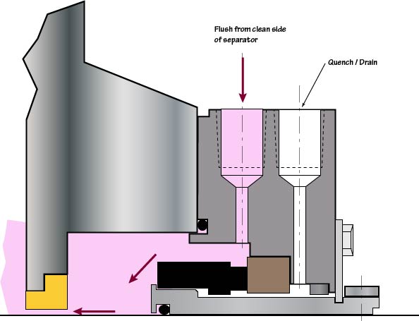
Throat bushings are a requirement when using this piping plan in order to isolate the cleaned up seal chamber from the dirty pumpage. To size and select the throat bushing and flowrate of clean fluid, the rule of thumb is that the velocity of the fluid passing through the throat bushing be on the order of 15 ft/sec to prevent the particles from entering the seal chamber. The flow rate of the clean fluids will dictate the type of bushing required. Floating bushings with close clearances should be used on low flow rate applications.
The maximum particle size in the pumpage should be less than 1/4 the size of any orifice, including the separator inlet ports; typically, this means that solids should be less than 1/32 to 1/16 inch in diameter.
Erosion can be a problem with Plan 31 because of the high velocities inside the separator. The combination of heavy solids and high velocities can cause erosion of the cyclone separator; however, rapid erosion is not a common problem when the recommended application guidelines are followed. An eroded separator is not as effective as a new separator and also has different flow characteristics. Therefore, the onset of erosion can be noted by changes in pressures in the Plan 31 system as well as the presence or evidence of solids in the seal chamber.
Most people do not realize that the cyclone separator in Plan 31 works best when the clean and dirty outlets – meaning the outlets at the separator itself — are at about the same pressure. For this reason, Plan 31 really needs pressure gauges, orifices and/or control valves. However, neither the API schematics nor my own illustrations show these gauges, orifice and valves. Here’s a new illustration that I’ll be using.
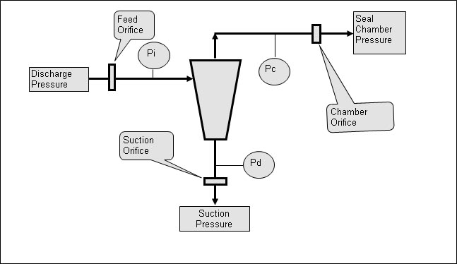
A cyclone separator needs at least a 15 psi differential to work well. However, if there is too much total differential pressure across the separator, then the centrifugal “streamlines” inside the separator become confused/turbulent and the separator does not work well. Typically, a maximum total differential pressure of around 200 psi across the separator is recommended. The orifices are used to set and control the pump differential pressure to be acceptable to the separator.
Even when designed and installed properly, Plan 31 does not remove all the solids from the pumpage (dirty) stream. For example, performance might be stated as something like “cyclone separator will remove 90% of all heavy solids having a diameter of 10 microns or larger.” By “heavy” is meant that the solids should have a density more than twice that of the liquid. Also, the concentration of solids should be less than 10%. In addition, the cyclone separator does not do well in viscous fluids.
When to use Plan 31?
Plan 31 should be considered when the fluid being pumped contains an amount of solids that might be detrimental to the long term performance of the mechanical seal. The question is “What amount of solids is detrimental to the performance of the seal?” Unfortunately, the answer is “Virtually any amount!”
Many times Plan 31 is added after the fact as a result of a failure analysis. In such cases, the recommendation to change to Plan 31 is likely to be the result of observing an accumulation of solids in or around the seal. Noting extreme abrasive wear on the seal faces could be another reason for recommending Plan 31. Unfortunately, those face observations are often misleading.
Selection of the proper abrasives separator has traditionally been done with a performance chart from the OEM based on their tests.
I’ve removed more Plan 31 systems than I’ve added but Plan 31 can work. The only one that I’ve personally known to solve a problem was in a river water pump. The water had so much sand in it that sand was deposited in the seal chamber and could be seen when the pump was disassembled. Plan 31 was added and essentially solved the sand problem. My guideline became “If dirt is being deposited in the seal chamber then change to Plan 31.” I’ve also seen demos and lab tests showing that Plan 31 can work but the key is to know and control the differential pressures.
Long ago, I was called on to troubleshoot a pump/seal having a Plan 41 (Plan 31 with a heat exchanger). To my surprise, I discovered that there was no flow to the seal. Instead, flow was from the seal chamber to the cyclone and then to pump suction. (I found this by feeling around the heat exchanger for differential temperatures.)
Advantages
- Solids are removed from the flush stream keeping the seal chamber clean.
- Unlike a strainer or filter the abrasive separator does not have to be cleaned.
Disadvantages
- The abrasive separator and the piping in the dirty outlet leg can become worn over time from the abrasives spiraling down the coned shaped bore.
- Not effective for removing low density solids such as coke fines.
- It is sometimes difficult to obtain the minimum pressure differential required for the abrasive separator to operate efficiently.
- Excessive differential pressures will cause the separator to not function properly.
- Unless the pressure differential from the two discharges to the final sources are roughly equal, the separator can either starve the seal or allow abrasives to flow into the chamber.
- Not advisable on low vapor margin applications as vapor bubbles have a more natural inclination to be channeled into the seal flush connection.
- Less effective with viscous fluids.