Plan 31 and Cyclone Separators

Although mechanical seals are used in all sorts of dirty fluids, it is well established that reliability is best when the fluid is clean.  Therefore, there is a great incentive to provide a clean fluid flush for seals in dirty services.  Piping Plan 31 is intended to clean up a dirty fluid to provide a clean flush to the seals.  Frankly, I don’t particularly care for Plan 31 and have rarely used or recommended it.

Plan 31
Plan 31

Recently I was asked a question about Plan 31 and realized that my description in SealFAQs was somewhat lacking so I’ll be revising and expanding that page.

Plan 31 relies on a “cyclone separator”, sometimes called an “abrasive separator”, or “hydrocyclone” to remove the dirt from the process fluid.  I’ve always preferred the term “cyclone separator” because it gives me a mental image of how the separation works.

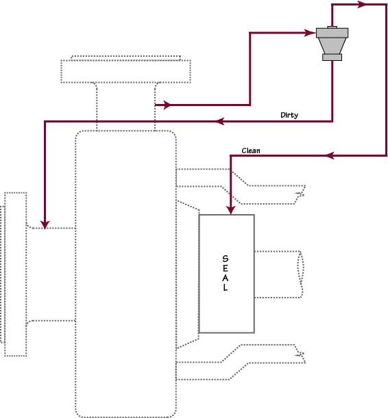
In Plan 31, the pumped (dirty) product flows to a cyclone separator from the discharge of the pump.  The cyclone separator, uh, separates the pumpage into clean and dirty streams by using centrifugal force.  The clean fluid stream is routed out the top of the separator and into the seal chamber while the now concentrated dirty fluid stream is routed back to pump suction.  Roughly speaking, the clean and dirty steams are approximately equal in flow rate; that is, a 50/50 split.

The late Robert Watkins of Chevron absolutely hated Plan 31.  More specifically, he hated cyclone separators.  One day Robert and I were teaching a seals class when, to my astonishment, I realized that Robert was saying that a cyclone separator should be purchased for every pump!  He then laughed and said “… and it should be fastened to the motor with baling wire!”  His theory was that, after having bought a cyclone separator for each pump, the seal salesman would leave him alone.  Plus, he could look everyone in the eye and say “Yes, we have a cyclone separator at that pump.”

I’ve removed more Plan 31 systems than I’ve added but Plan 31 can work.  The only one that I’ve personally known to solve a problem was in a river water pump.  The water had so much sand in it that sand was deposited in the seal chamber and could be seen when the pump was disassembled.  Plan 31 was added and essentially solved the sand problem.  My guideline became “If dirt is being deposited in the seal chamber then change to Plan 31.”  I’ve also seen demos and lab tests showing that Plan 31 can work but the key is to know and control the differential pressures.

Most people do not realize that the cyclone separator in Plan 31 works best when the clean and dirty outlets – meaning the outlets at the separator itself — are at about the same pressure.  For this reason, Plan 31 really needs pressure gauges, orifices and/or control valves.  However, neither the API schematics nor my own illustrations show these gauges, orifice and valves.   Here’s a new illustration that I’ll be using.

Plan 31 with Orifices

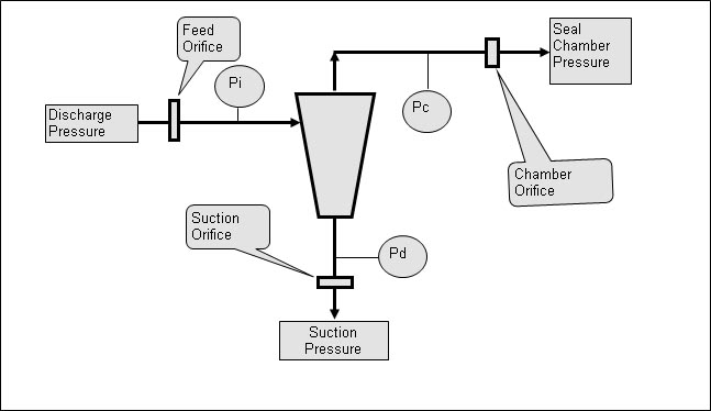
A cyclone separator needs at least a 15 psi differential to work well.  However, if there is too much total differential pressure across the separator, then the centrifugal “streamlines” inside the separator become confused/turbulent and the separator does not work well.  Typically, a maximum total differential pressure of around 200 psi across the separator is recommended.  The orifices are used to set and control the differential pressure across the separator.

Long ago, I was called on to troubleshoot a pump/seal having a Plan 41 (Plan 31 with a heat exchanger).  To my surprise, I discovered that there was no flow to the seal.  Instead, flow was from the seal chamber to the cyclone and then to pump suction.  (I found this by feeling around the heat exchanger for differential temperatures.)

Even when designed and installed properly, Plan 31 does not remove all the solids from the pumpage (dirty) stream.  For example, the performance might be stated as something like “cyclone separator will remove 90% of all heavy solids having a diameter of 10 microns or larger.”  By “heavy” is meant that the solids should have a density more than twice that of the liquid.  Also, the concentration of solids should be less than 10%.  In addition, the cyclone separator does not do well in viscous fluids. 

So I don’t particularly like or recommend Plan 31.

TRL, API RP-691 and API 682

“TRL” is an acronym for Technology Readiness Level.  This is a new acronym for me.  I’m trying to learn more about it and its implications for mechanical seals — especially for API 682 5th Edition because the API lawyers are insisting that the TRL method and reference to RP-691 be added to API 682 5th Edition.

API RP-691 is a Recommended Practice from the American Petroleum Institute (API).  An API Recommended Practice is a document that communicates recognized industry practices.  In contrast to a Recommended Practice, an API standard appears to be much more binding and rigid.  API standards typically include references to Recommended Practices.

API RP-691 is titled “Risk-based Machinery Management”.  This 198 page document was published in June 2017 and is in its first edition.  It is available through API; costs $163 and can be purchased here.  Although I do not have a copy (and, apparently, API will not give a complimentary copy to the API 682 Task Force), RP-691 does not appear to have specific recommendations for mechanical seals.  It does, however, include pumps.  A preview of RP-691 is available here.  Be sure to click on the “Look Inside” icon to get a preview of RP-691.

In its description, RP-691 is said to define “the minimum requirements for the management of health, safety, and environmental (HSE) risks across the machinery life cycle. It shall be applied to the subset of operating company and/or vendor defined high-risk machinery.”  The proposed seal standard, API 682 5th Edition, certainly includes high risk machinery as defined in RP-691:  high temperatures, pressures exceeding 600 psig and specific gravities less than 0.5 even though all services may not be high risk.

From other sources, I learned that Technology Readiness Levels range from TRL 0 to TRL 9 with TRL 0 marking the beginning of research and TRL 9 being proven technology.  API appears to be assigning TRL 7 to machinery that has been used successfully in the field for three years.  That being the case, seals having been successfully Qualification Tested per API 682 would probably be assigned TRL 5 or TLR 6 but I’m just guessing at this point.

I have no objection to API inserting the reference to RP-691 into API 682 and it wouldn’t matter if I did.  I understand that the new TRL clauses are written somewhat generically in order to be inserted into other API standards as well.  I was told that the same clauses would be inserted into the next edition of the pump standard, API 610.  The API 682 Task Force was told that the paragraphs referencing RP-691 were mandatory and could not be edited or revised.  My concern is that, as written, the new clauses appear to completely overlook the Qualification Tests of API 682 and leave evaluation up to the judgement of the purchaser.  

Technology Readiness Level especially irritates me because, during the development of API 682 1st Edition, we were specifically told that field experience did not count.  As a result, the seal OEMs were forced into conducting expensive Qualification Tests by the API some 25 years ago and have spent many man-hours and millions of dollars on those tests.  If the TRL requirements had been available/required at the time of developing  API 682 1st Edition, not only would those requirements have been incorporated into the 1st Edition but there would have been no reason for developing, much less conducting, the Qualification Tests.  

Mechanical seals are a mature and proven technology.  Every seal OEM almost certainly has products that have been around for 30 – even 60 years – and also has many end users that have achieved 6 to 8 year MTBR with their products.  Therefore, a TRL rating of 7 for mechanical seals will quickly become the norm.  The TRL requirements will soon be taken for granted and become meaningless and ignored except that the TRL will take precedence over the Qualification Tests.

Obviously, passing a Qualification Test will not and should not result in a TRL higher than the rating of 7 granted for 3 years of actual service.  That being the case, why should a seal OEM bother with the Qualification Tests at all? I predict the demise of the API 682 Qualification Tests.

Here are some links for information about Technology Readiness Levels (TRL):

https://www.nasa.gov/directorates/heo/scan/engineering/technology/txt_accordion1.html

https://en.wikipedia.org/wiki/Technology_readiness_level

https://www.ncbi.nlm.nih.gov/books/NBK201356/

http://www.airforcemag.com/MagazineArchive/Magazine%20Documents/2016/August%202016/0816infographic.pdf

Thrust Load from Seals

The pressure surrounding the mechanical seal and its shaft sleeve imposes an axial force – a thrust – on the shaft.  This thrust load and direction can be determined by summing the products of the various pressures and areas of the seal and sleeve.  Fortunately, many of these products cancel each other out and the thrust load can be computed in a simple manner. 

The method shown below for calculating thrust load is taken from Chapter 17, “Seal Thrust Loads on Pump Shafts”, of Mechanical Seals for Pumps:  Application Guidelines from the Hydraulic Institute and Fluid Sealing Association.   Only the thrust load for single pusher seals is shown in this post but the book includes dual seals and bellows seals.

The general idea is that there is a hydraulic area between the balance diameter of the seal and the shaft upon which the seal chamber pressure acts to produce an axial thrust.  This hydraulic area is given by

where

    • A is the hydraulic “thrust” area, inch2
    • Db is the balance diameter of the seal, inch
    • Ds is the OD of the shaft, inch.

The thrust force is the product of the seal chamber pressure and thrust area.

The location of the balance diameter is illustrated below.

For many seals, the balance diameter can be estimated from the shaft size as follows:

  • Classic rotating seal:  shaft diameter plus 1/2” to 5/8”
  • Inverted rotating seal (made into stationary seal):  shaft diameter plus 5/8” to 1”
  • Stationary seal:  shaft diameter plus 5/8” to 1”.

These approximations to the balance diameter can be made because, typically, radial thicknesses, radial steps and even O-ring cross sections are based on 1/8” increments.  Radial clearances are often based on 1/16”; seals with large radial clearances may also have larger balance diameters.  Another variation comes from the shaft diameter not being an exact 1/8” increment and the sleeve may be used as an “adapter”.  Of course, the exact balance diameter depends on the seal design, thicknesses, clearances, etc. and the seal manufacturer should be consulted.

So, how much thrust is produced by the seal?  Sometimes, quite a lot – especially for large seals at high pressures.  The graph below is based on a classic rotating seal with balance diameter 1/2” larger than the shaft and a stationary seal with balance diameter 3/4” larger than the shaft.

Obviously, the thrust load estimated here for a stationary seal exceeds that of a rotating seal but this may not always be the case.  Again, the details of the seal design must be checked.  However, it is often the case that the thrust load from a stationary seal is larger than that from a rotating seal; therefore, it is best to consider a stationary seal configuration when making general assumptions about thrust loads.

This thrust load is transmitted to the shaft – typically by set screws – but devices such as pins, slots, grooves, split rings, etc. are sometimes used.  Therefore this thrust load is added to the thrust load imposed on the pump bearings.  Note that if the pump uses two seals (one on the driven end and one on the non-driven end) then the net thrust load from the seals that is imposed on the bearings may be zero.

Eventually, this blog post will make its way into the design pages of SealFAQs.  In a later post, we’ll take a look at the thrust capacity of set screws.