
Heat exchangers are often used in mechanical seal systems and piping plans to provide a cooler environment for the seal. In general, three types of heat exchangers are used:
- water cooled
- air cooled (natural draft)
- air cooled (forced draft).
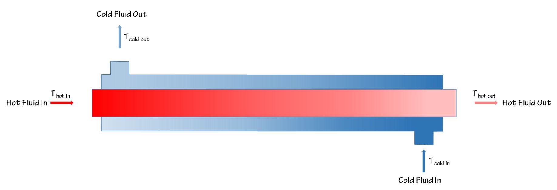
The basic concept of a heat exchanger can be viewed as a tube with one fluid running through it and another fluid flowing by on the outside. This is the case whether the heat exchanger uses water or air for cooling although, of course, the actual exchangers are different in appearance.
An air cooled heat exchanger is almost certain to use “fins” that are wrapped around a tube.
In general, calculations are built around a simple equation:
Heat Transferred = U x A x LMTD
Where
U is the overall heat transfer coefficient
A is the heat transfer area of the exchanger
LMTD is the Log Mean Temperature Difference.
However, for air cooled heat exchangers, instead of LMTD, the average differential temperature between the hot process fluid and ambient air is used.
For estimating purposes, so called “handbook” values for U are often used. For natural draft air cooled heat exchangers, the overall heat transfer coefficient, U, typically ranges from 0.5 to 2 Btu/hr sq ft F. Small heat exchangers tend to have the larger U value. High process flow rates promote larger U values. The limiting factor is convection to air so to allow for a calm day, use the smaller value.
The procedure for estimating an approximate heat exchanger design and size is:
- Estimate the “U” value
- Estimate the LMTD to be the average temperature difference between the air and the process fluid.
- Determine the heat transfer duty to attain the process fluid temperature drop
- Calculate the necessary heat transfer area for the air cooled heat exchanger.
For the majority of heat exchanger applications, the above procedure will provide a reasonable selection.
Pressure Drop
In general, pressure drop is roughly proportional to flow rate squared but also varies with viscosity. Each exchanger should have a base case pressure drop for reference.
Pressure drop inside tubing can be estimated using standard pipe calculations; however, coiled tubing produces a higher pressure drop than straight pipe.
In some exchangers, a “turbulator” is used to promote turbulent flow and improved heat transfer. The turbulator also causes an increase in pressure losses.