
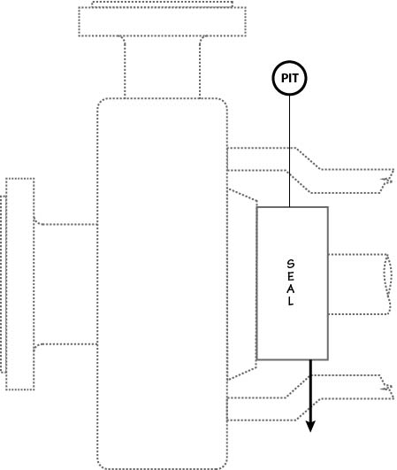
Plan 66A is a new leakage detection system in 4th Edition of API 682 that is also designed to minimize seal leakage to atmosphere. Plan 66A was designed initially for pipeline applications with single seal installations.
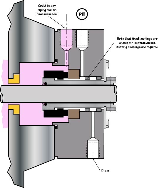
Plan 66A cannot be adequately described with only the above schematic. Plan 66A uses two throttle bushings in series. During normal operation leakage can freely flow through the drain port located past the first bushing. When leakage is excessive the inner bushing will restrict the flow to the drain and the second bushing will limit the amount of leakage leaving the gland. With increasing leakage rates the pressure on the upstream side of the inner bushing will increase. The pressure increase will be sensed by the pressure transmitter and set off an alarm indicating a seal failure. Leakage exiting the drain port can be collected and piped to a sump or liquid recovery system.
Although the concept of Plan 66A is that leakage could be monitored, it is more likely that only significant leaks could be detected. To illustrate this, consider the following mathematical model.
In Plan 66A, the seal chamber pressure, P1, is reduced to pressure P2 by the flow resistance of the seal face and and built up by the flow resistance of the inner bushing. There is no flow to the pressure transmitter which measures pressure P2. Note that all seal face leakage must pass through the inner throttle bushing which reduces pressure P2 to pressure P3. Pressure P3 must be high enough to force the seal face leakage through the outer throttle bushing and drain. The computational procedure is to estimate P2 and then calculate P3 and the various flows. This trial and error procedure is repeated until convergence is obtained. It should be noted that, for some cases, the numerical values are quite small and perhaps not realistic. Even so, trends can be observed.
An example of the mathematical model is shown below.
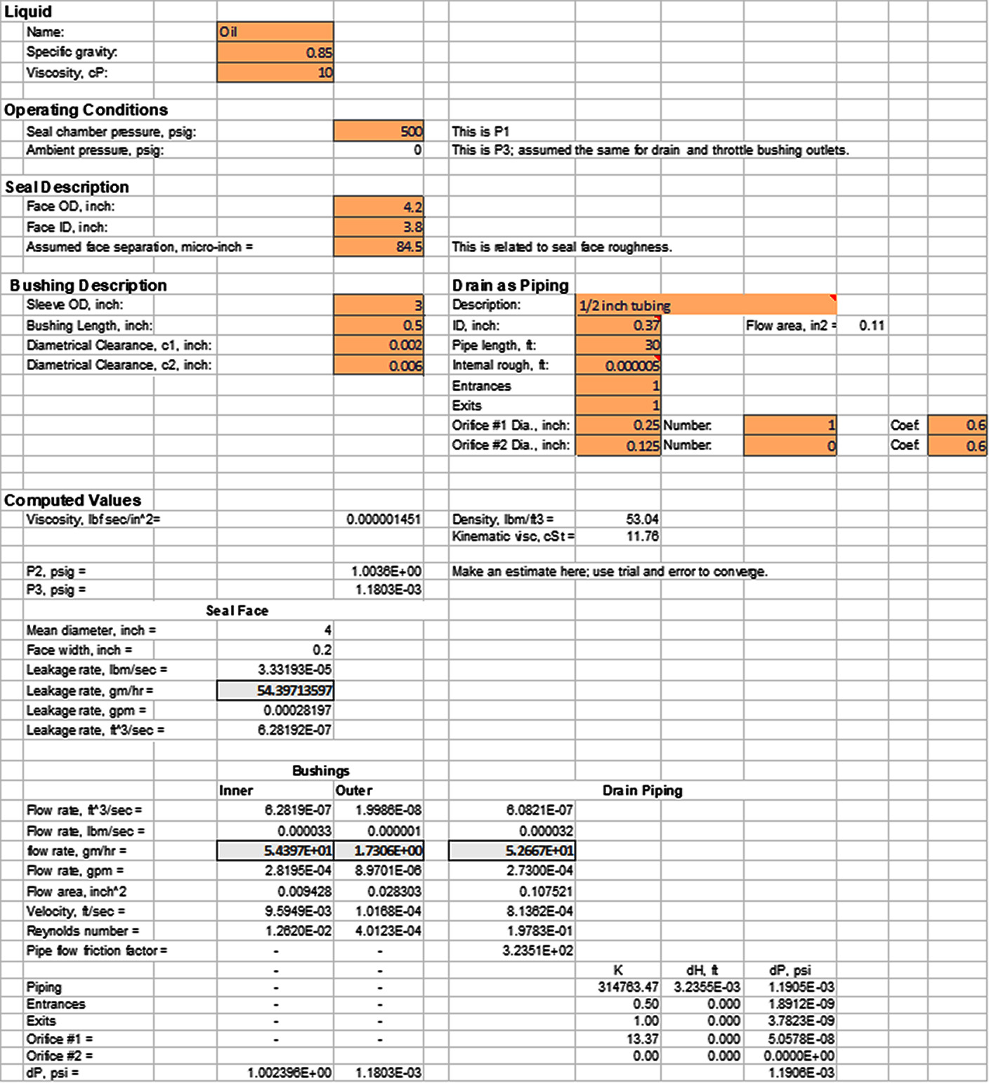
Example using Plan 66A
Suppose that Plan 66A is applied to the conditions shown in Figure 5 and that a leakage rate of 3 gm/hr is acceptable but 30 gm/hr is not. Using Piping Plan 66A, what alarm pressure represents 30 gm/hr seal face leakage?
What alarm pressure is needed to detect 30 gm/hr seal face leakage using Piping Plan 66A?
Answer: 0.55 psig (details not shown)
What seal face leakage rate will trigger a 1 psig alarm? What is the throttle bushing flowrate?
Answer: 54 gm/hr (0.00028 gpm) total leakage; 1.7 gm/hr from the throttle bushing (details shown above).
Suppose that the outer throttle bushing clearance is 0.002 inch instead of 0.006 inch. What seal face leakage rate will trigger a 1 psig alarm? What is the throttle bushing flowrate?
Answer: 54 gm/hr (0.00028 gpm) total leakage; 0.067 gm/hr from the throttle bushing (details not shown).
The graphs below shows seal face leakage rates, pressure rise and throttle bushing leakage for various configurations of Piping Plan 66A. All cases had 0.006 inch diametral clearance for the outer bushing and 96 to 97% of the seal face leakage went to the drain.
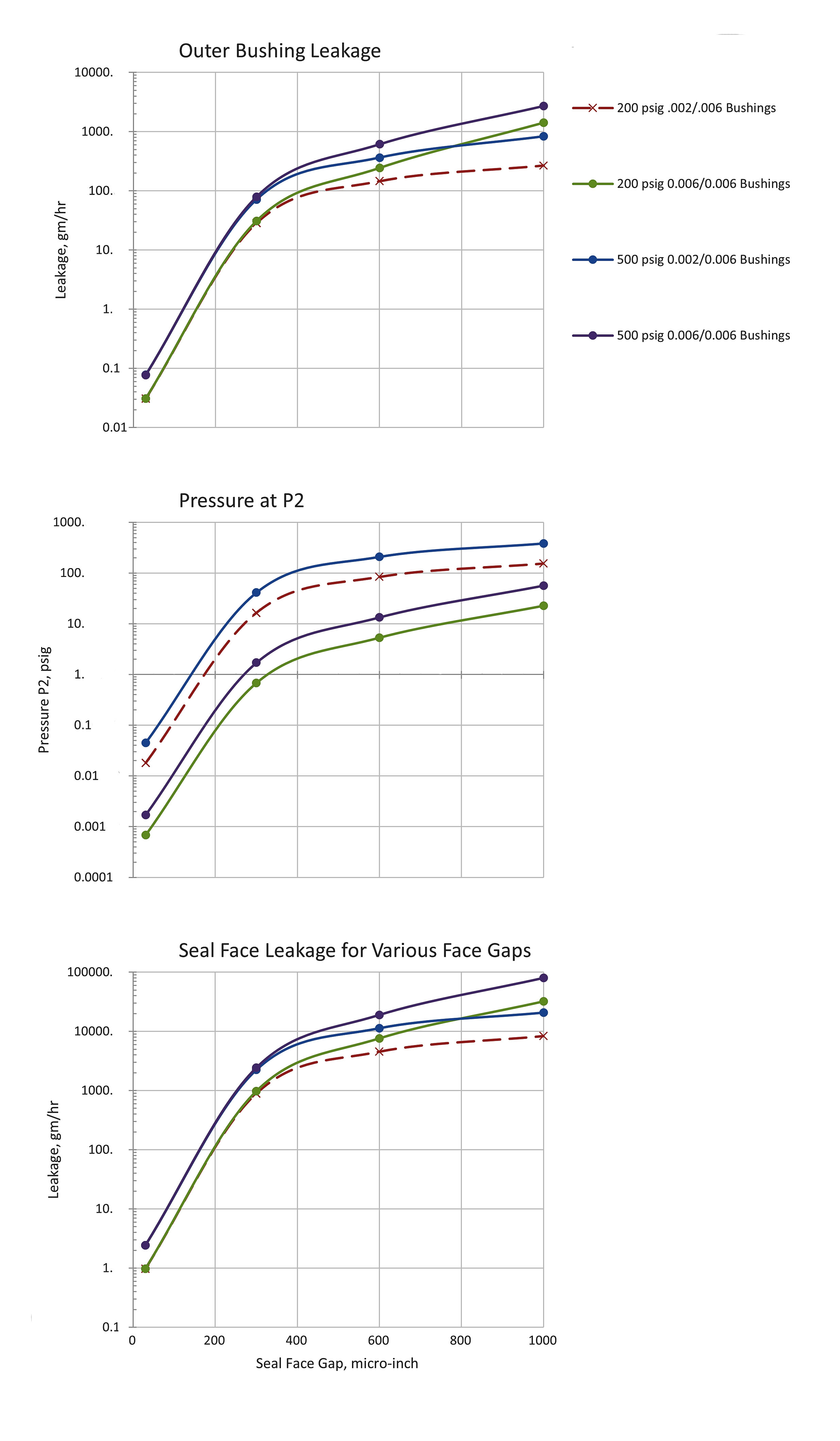
In particular, notice that the pressure P2 remains very low except in cases of very high seal face leakage rates.