
Although this page of SealFAQs might be called theory by some, it actually contains independent application engineering computations that provide useful guidance as well as rationale to a skilled engineer. Many of these calculations are available in engineering handbooks in other forms and have been recast for use with mechanical seals.
It is the responsibility of the user to apply and interpret the results of these calculations.
Contents
- Assumptions
- Leakage
- Wear
- Forces and Face Loads
- Hydrodynamic Effects
- Pressure Gradient Factor
- Heat Generation and Transfer
- The Duty Parameter
- Nomenclature
Assumptions
Calculations are based on the following assumptions:
- Axisymmetric.
- Constant seal face temperature but axial temperature gradients may exist.
- Newtonian liquids.
- Ideal gases.
- Seal face width less than 10% of the mean radius.
- Seal faces are flat with isotropic roughness.
- Seal face separation may have parallel, converging or diverging leakage paths.
- Mechanical contact, hydrostatic and hydrodynamic forces provide seal face load support.
Leakage
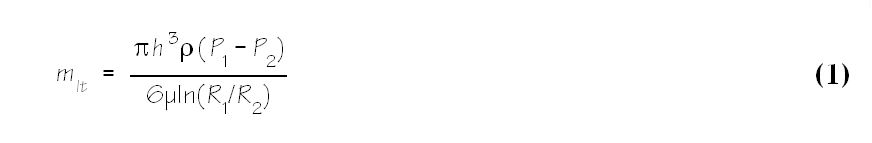
The purpose of the seal is to prevent leakage but all seals leak to some degree. For liquids, the leakage rate is proportional to the pressure and may be calculated from Equation 1.
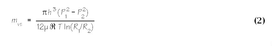
 For gases, use Equation 2.
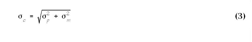
 The seal face gap, h, is the same order of magnitude as the combined surface roughness of the primary ring and mating ring. The combined roughness is
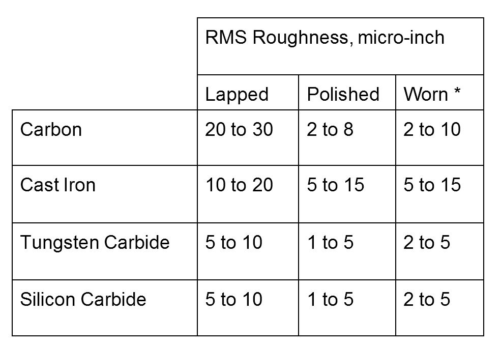
 Surface roughness vary widely but typically fall in the range shown in the table below.
To get a feeling for leakage, consider that an emission rate of 1000 ppm is a mass leakage rate of about 5.6 grams per hour. Another rough rule of thumb is that a milliliter of liquid contains about twenty drops; therefore, a volumetric leakage rate of 6 milliliters per hour would be about 120 drops per hour — two drops per minute.
Wear
Much of mechanical seal application engineering is concerned with the tradeoffs between leakage and wear. A decrease in wear is often accompanied by an increase in leakage and vice versa. By using modern materials and designs, excessive wear is neither a problem nor a failure mode for the vast majority of mechanical seals. On the other hand, the possibility of excessive wear should always be checked.
For mechanical seals, wear may be caused by adhesive, abrasive or chemical processes. The most common wear process is adhesive wear which occurs between the seal faces as the tips of the asperities contact and break away from the parent material.
For mechanical seals, just as for other wear devices, the amount of adhesive wear that occurs is
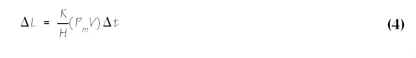 The value of the wear coefficient, K, varies considerably and is certainly influenced by abrasion and chemical processes. It appears that no single value for the wear coefficient is adequate to describe the wear behavior of carbon graphite. Although appropriate hardness values are readily available for metals, similar information for carbon graphite is not so available. For these reasons, the ratio, K/H, is usually used instead of the separate parameters. This ratio is a strong function of the tribological mating pair as well as the fluid. It has been reported to vary from 10-14 to 10-16 1/psi.
A useful value to remember is that a wear rate of 0.0007 inches in 100 hours extrapolates to a wear length of 1/8 inch after two years. API 682 requires a total wear of less than 1% of the available length during its Qualification Tests. However, wear is not linear with time and most wear probably takes place during the first 100 hours or less.
Effect of Fluids on Wear Rate
It is well known that, under apparently similar conditions, the rate of wear in mechanical seals is highly dependent on the fluid being sealed. Some of this is due to the effect of the physical properties of the fluid on the mechanical contact pressure, Pm. For example, viscous fluids, such as lube oils, increase hydrodynamic lift thus reducing the mechanical contact pressure and therefore reducing wear. An engineering analysis which includes hydrodynamic load support will include the effects of the physical properties of the fluid. In other words, the simplest assumption is that the ratio of wear coefficient to hardness, K/H, does not vary from fluid to fluid. Therefore the procedure is to use the steady state value for K/H from water tests if no other information is available.
Because of the effects of chemistry, it is best to use K/H values based on identical or chemically similar fluids. However, this often is not possible and good engineering judgement must be used.
Some fluids, notably liquified gases, appear to prevent the formation of a carbon graphite film on the mating face. For these fluids, the value of K/H might be significantly higher than otherwise expected.
Effect of Abrasive Solids on Wear Rate
The wear rate can be greatly increased if abrasive particles are in the fluid. Abrasive wear can also be evaluated by using Equation 3-1 with an appropriate value for K/H; however, there is so much variation in K/H under abrasive conditions that it is impossible to generalize.
Forces and Face Loads
As shown by Equations 1 and 2, the leakage rate and therefore the success of the seal depend on maintaining a very small seal face gap, h, between the rotating and stationary faces. In order to assure that this gap is small, the net closing forces acting on the seal must have a positive gradient with respect to the face gap.
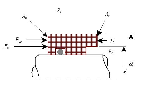
Figure 1 shows a typical primary ring. In Figure 1, the face area, Af, lies between the outer radius R1 and the inner radius R2. A fluid is at the outer radius under pressure P1. Fluid is also present at the inner radius under pressure P2. Typically, the fluid being sealed is at the outer radius and P1 is greater than P2; however, this is not a requirement. Usually the fluid being sealed is a liquid and the fluid being protected is atmospheric air. In Figure 1 the radii and pressures are numbered to indicate that leakage flow goes from point 1 to point 2 and the fluid is at state points 1 and 2.
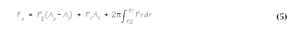
Any pressure forces on the face area, Af, tend to increase the seal face gap and are called opening forces. For the same reason, sometimes the seal face area is called the opening area. This opening force, Fo, has three components as shown in Equation 5. The pressure P2 exerts a force P2(Ac – Af) on the area below the seal face. Pressure is also distributed over the seal face both hydrostatically and hydrodynamically. Integrating the hydrostatic pressure distribution over the seal face area produces a hydrostatic component of the opening force. Most seals operate with some combination of hydrodyamic and mechanical contact. For historical consistency, at this point, we combine the hydrodyamic and mechanical contact forces into one term, PfAf.
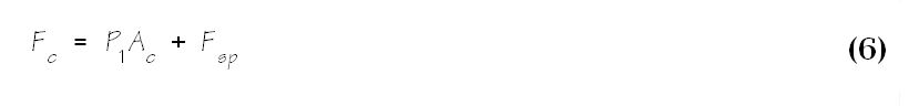
The closing force, Fc, has two components as shown in Equation 6. The sealed pressure, P1, acts on the area at the end of the seal, Ac, to exert a closing force P1Ac. For most seals, a mechanical spring force, Fsp, also acts on Ac to provide an initial closing force.
 For steady state operation, the opening and closing forces are equal, therefore the average face pressure, Pf , may be found by equating Equations 5 and 6.
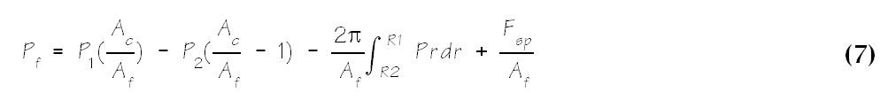
If Pf is positive, there may be direct rubbing between the rotating and stationary faces; this is a condition of low leakage. For Pf to be negative, the opening forces have overcome the closing forces and leakage may be high.
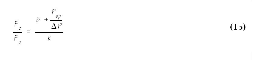
Equation 7 is cumbersome to use but is basic to an understanding of mechanical seal design. The determination of the average face pressure, Pf, is simplified by defining a pressure gradient factor, k, and a balance ratio, b.
Hydrodynamic Effects
Equation 13 is the classic equation for computing the average seal face pressure. When this relationship was first developed, Pf was considered to be the average mechanical contact pressure and many technical papers on mechanical seals still use Equation 13 for average mechanical contact pressure. However, considering the derivation of this equation, it is apparent that Pf must also include the average hydrodynamic pressure. That is
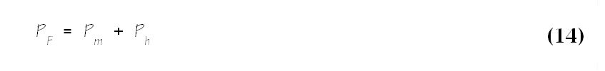
For some applications, particularly those with low viscosity fluids and/or low speeds, the hydrodynamic effects are small and Pf = Pm. On the other hand, it is increasingly apparent that the hydrodynamic effects must be considered in many applications. Calculation of the hydrodynamic load support is beyond the scope of this simple theoretical approach.
It is not necessarily conservative to assume that there are no hydrodynamic effects. For example, the hydrodynamic load support could be so strong that there is no mechanical contact and leakage might be excessive.
Hydrodynamic effects may be enhanced through the use of various face treatments such as Raleigh pads, hydropads, spiral grooves, etc but such effects are beyond the scope of this report.
Pressure Gradient Factor
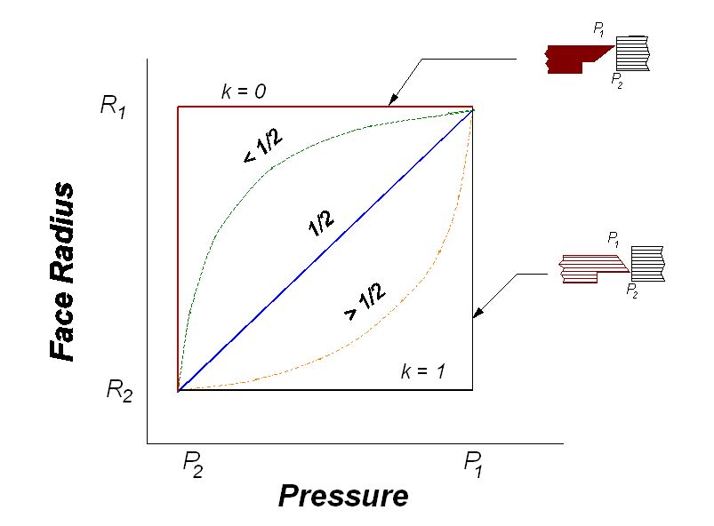
Equation 7 can be made less formidable by replacing the quantity to be integrated with a simple algebraic quantity. The pressure gradient factor, k, is defined such that
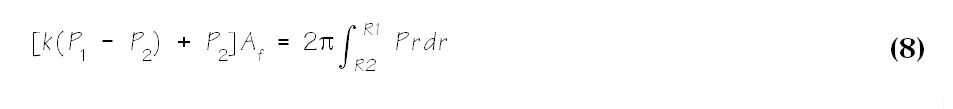
then k = 0 when the fluid pressure is P2 over the entire seal face; k = ½ for a linear pressure drop across the seal face and k = 1 for the fluid pressure at P1 over the entire face. Figure 2 illustrates this relationship between the pressure gradient factor and pressure distribution. For an incompressible fluid, k = /( + 1) where = h1/h2, the ratio of inlet to outlet face separation. This concept is also shown in Figure 2 where k = 0 for line contact at the seal outside diameter and k = 1 for line contact at the inside diameter when the pressure to be sealed is at the outside diameter.
For compressible fluids, the pressure profile between two parallel plates is approximately parabolic and may be expressed as
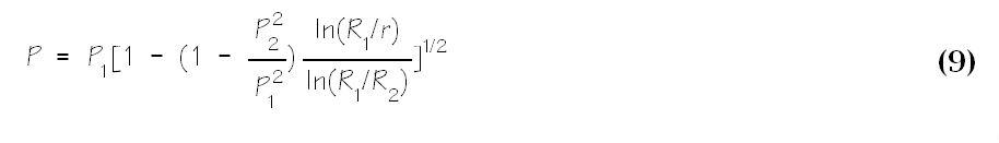
Substitution of Equation 8 into Equation 7 yields
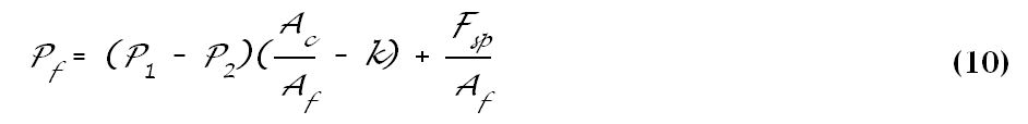
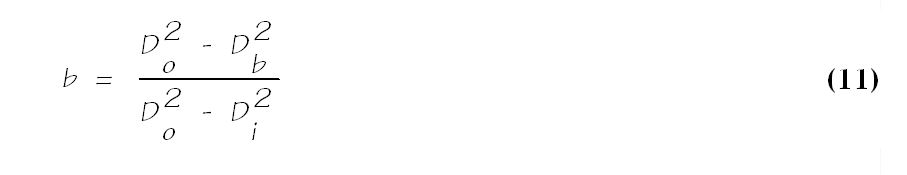
Equation 10 can be further simplified by defining the geometric balance ratio, b.
The quantity Ac/Af in Equation 10 is defined as the seal geometric balance ratio, b. For seals pressurized from the outside diameter
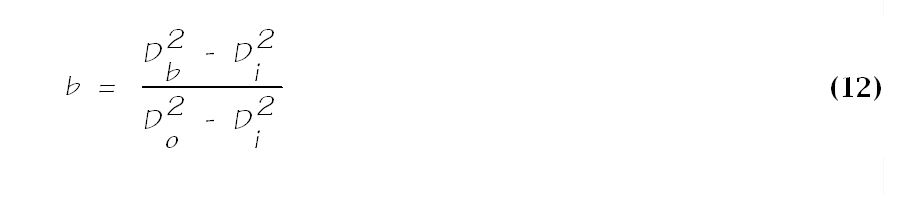
If the seal is pressurized from the inside diameter, then equation 10 still applies; however, in terms of diameters
Using the definition of balance ratio, Equation 4-6 is reduced to the frequently used form of Equation 13.

The geometry of the seal nose and shaft can be manipulated to obtain b < 1 or b > 1 to change face loading. Seals with b > 1 are called unbalanced or over-balanced seals; seals with b < 1 are called balanced seals. The phrase “balanced seal” is misleading and only indicated a lower face pressure than a similar “unbalanced” seal by virtue of geometric manipulations.
A seals with b = 1 is impractical with a constant diameter shaft because there would be no clearance between the seal inside diameter and shaft. In practice unbalanced seals have balance ratios ranging from around 1.1 to around 1.4. Balanced seals are used with a stepped shaft and are typically designed for b = 0.6 to 0.9.
The face pressure generated by the spring, Psp, is usually in the range of 20 to 40 psi. Because of the seemingly low value for spring pressure, it is sometimes neglected in seal calculations. This may be an error, especially in low pressure applications where the spring pressure is the same magnitude as the hydraulic pressure.
The average face pressure, Pf , from Equation 13 must be positive for the faces to be in contact. In order to have minimum leakage, the seal should be designed for a positive face load; however, an increase in face load may also mean an increase in heat generation.
Constraints on Hydrostatic Forces
An engineering practice is to neglect hydrodynamic and contact effects and use a safety factor for the ratio of remaining closing force to hydrostatic opening force. This rule of thumb and subsequent analysis does not consider the effects of O-ring drag. Therefore, a different safety factor is used for pusher and non-pusher seals. A safety factor of 1.1 to 1.5 is used as the minimum ratio of closing force to opening force for pusher seals in normal operation; for non-pusher seals, the minimum is 1.1 to 1.3.
The average face pressure, Pf, should be kept below 1% to 2% of the compressive strength of the softer face material. This is regardless of any hydrodynamic effects that might occur during operation because on startup there is no hydrodynamic effect.
Heat Generation and Transfer
Mechanical seals generate heat as the primary ring and mating ring rub together. Heat is also generated through viscous shear of the fluid film between the faces and around the rotating components. For low viscosity fluids, most heat generation is by rubbing. In this case, the coefficient of rubbing friction for the primary ring and mating ring pair determines the heat generation. For viscous fluids there may be no rubbing but viscous shearing may generate about the same amount of heat as if rubbing occurred. An important difference is that the wear rate is likely to be much greater when low viscosity fluids are between the seal faces.
Heat transfer plays an important role in seal performance. Both conduction and convection heat transfer are significant in mechanical seals. Conduction heat transfer is the process of heat transfer through solids. Convection heat transfer is the transfer of heat from the solid to the surrounding liquid.
Since heat generation takes place in the sealing interface, the first heat transfer process is through the primary ring and mating ring. The thermal conductivity of these materials is very important. Materials like silicon carbide and tungsten carbide have relatively high thermal conductivities. Materials like alumina (ceramic) and carbon graphite have much lower thermal conductivities.
Convection heat transfer takes place from the primary ring and mating ring to the surrounding fluid. Convection heat transfer is usually evaluated as having three components: a convection (or film) coefficient, wetted area and temperature difference. The convection coefficient is the combined effects of the fluid properties, rotational speed, seal chamber design, flushing design and flush rate. Low viscosities and high speeds promote high convection coefficients. It is very important to have enough wetted area so that heat transfer takes place without high temperature increases in the mating ring and primary ring.
For most seal designs, all generated heat enters the fluid surrounding the seal. This means that the fluid tends to increase in temperature. Unless the surrounding fluid is cooled or continuously replaced, it may become too hot for reliable seal performance. Most seals operate with continuous replacement of the surrounding fluid; this replacement process is called the seal flush, see Figure 3.
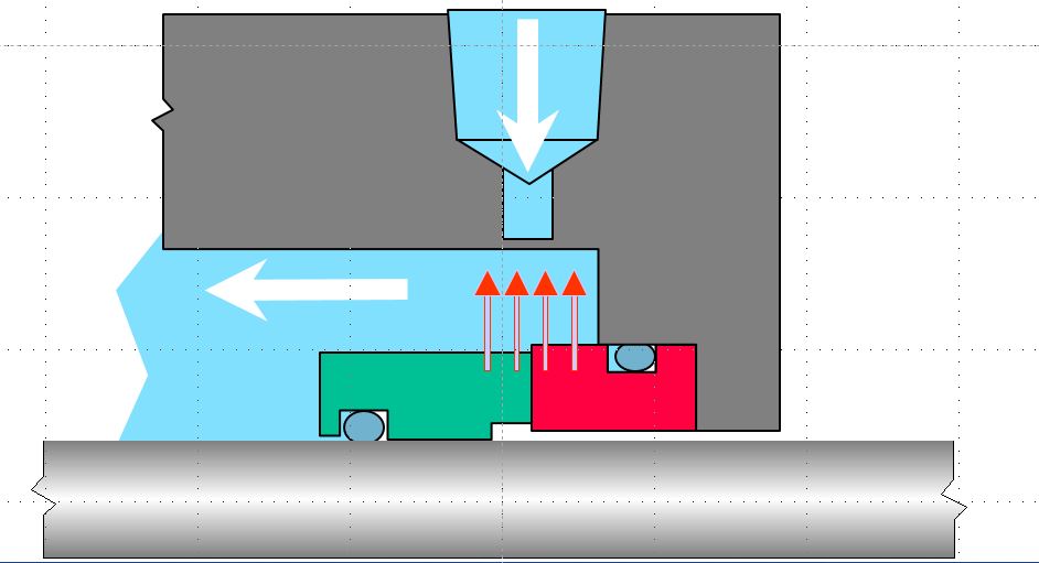
Seal flush rates are selected so that the fluid properties and average temperature remain satisfactory after removing all generated heat. Using this approach, a typical rule of thumb is that the average temperature rise should be less than around 5 °F for light hydrocarbons, 15 °F for water and 30 °F for oils. A simpler rule of thumb is that the seal flush rate should be about one gpm per inch of shaft size for water and non-flashing services but twice that rate for flashing services. A still simpler rule is to use two gpm of flush. It is important to note that all these rules of thumb give about the same results for the majority of actual seal applications in refinery and chemical plant pumps. Further, most of the time, the actual flush rate is greater than this guideline. Even so, many seal problems are related to the seal flush rate, design, location, etc; it is important to get the proper flush rate and system for each application.
There are many seal flush designs. The American Petroleum Institute has categorized and labeled the common systems; these API systems are usually called the API Piping Plans. The piping plan most often used is Plan 11 which uses injection from pump discharge to flush the seal. Figure 3 could be an example of a Plan 11 flush if the source of the injection were the pump discharge.
Heat Generation
Heat is generated by rubbing and viscous shear. Rubbing may occur between the seal faces. Viscous shear occurs between the faces and around the rotating components. The viscous shear around the rotating components is call churning. Churning is not included in the heat generation between the seal faces but should be considered as part of the overall heat load on exchangers, flush systems, etc.
The heat generated by rubbing is
 Heat generated between the faces by viscous shear is
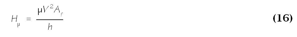
It is important to realize that the viscosity of the liquid between the seal faces is likely to be significantly less than the viscosity of the bulk fluid because the seal faces are at a higher temperature than the bulk fluid.
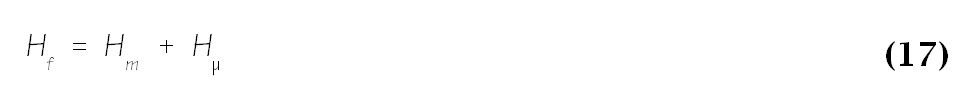
The total heat generated between the seal faces is the sum of the rubbing and viscous heat generation.
Heat generated by churning is considerable in some cases. It primarily is a function of peripheral velocity and fluid properties. In large seals handling dense fluids, heat generated due to churning may be larger than the heat generated at the seal interface. Computing the heat generated by churning is somewhat more complex than viscous shear or rubbing and is beyond the scope of this website.
Coefficient of Friction
Mechanical seal calculations can be considerably simplified through the use of a coefficient of friction.. Unfortunately, there are many definitions and derivations of the coefficient of friction. No matter what the source, definition or derivation, the coefficient of friction is not a constant. It ranges from around .03 to .3 and frequently is found to be around 0.1 for many applications. Naturally, the coefficient of friction is a function of the tribological material pair but it also depends on the fluid being sealed. To make matters worse, it turns out that the coefficient of friction also depends on the seal face load. Furthermore, the coefficient of friction is reduced when the seal leaks. In spite of these limitations, the coefficient of friction is a useful means of comparing seal face materials, especially when tests are done under similar conditions.
Great care should be used when working with coefficient of friction data, especially when working with data from different sources. The coefficient of friction is not measured directly; instead, it is computed based on measurements of heat generation or torque. A certain load, or basis of load, is assumed and the coefficient of friction is computed. The tests might use mechanical seals or other friction devices such as a pin on disk tester. Some tests using seals are based on pressurized seals but other tests might be in an unpressurized bath of fluid. Since the heat generation or torque is a result of both mechanical contact and viscous shear, the computed coefficient of friction includes both these effects. To avoid this problem, tests must be conducted at low speeds or with low viscosity fluids. Also, some mechanical seal researchers base the coefficient of friction on closing force instead of net force — that is, closing force minus opening force — and on mechanical contact pressure alone.
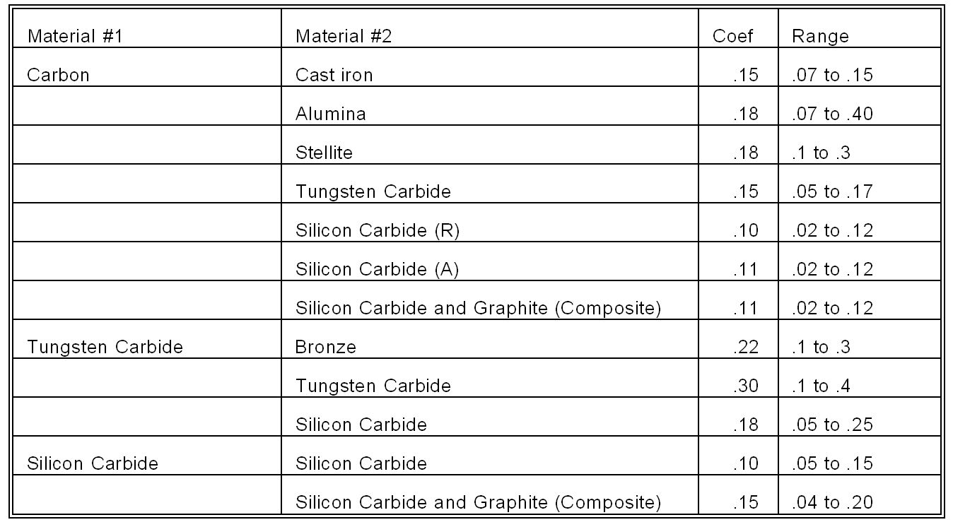
The table below shows representative values for the coefficient of friction for various face combinations.
The Duty Parameter
In the science of tribology, a dimensionless number, generally described as a “Duty Parameter”, is often used to correlate performance with regard to lubricity. There are several forms of the duty parameter. In particular, different forms are used to describe the performance of various machine elements.
The Classic Duty Parameter is a dimensionless number combining viscosity, speed, load and a characteristic length. It is sometimes called the Stribeck number, especially when it is illustrated along with a coefficient of friction.
By making changes so that hydrostatic load support is considered, the Duty Parameter becomes much more useful for correlating the performance of mechanical seals. This variation will be defined as the Seal Duty Parameter.
![]()
Equation 18 provides a useful indicator for seal performance within the range 1×10⁻⁹ to 1×10⁻⁴. Figure 4 shows how the friction coefficient varies with the Seal Duty Parameter.
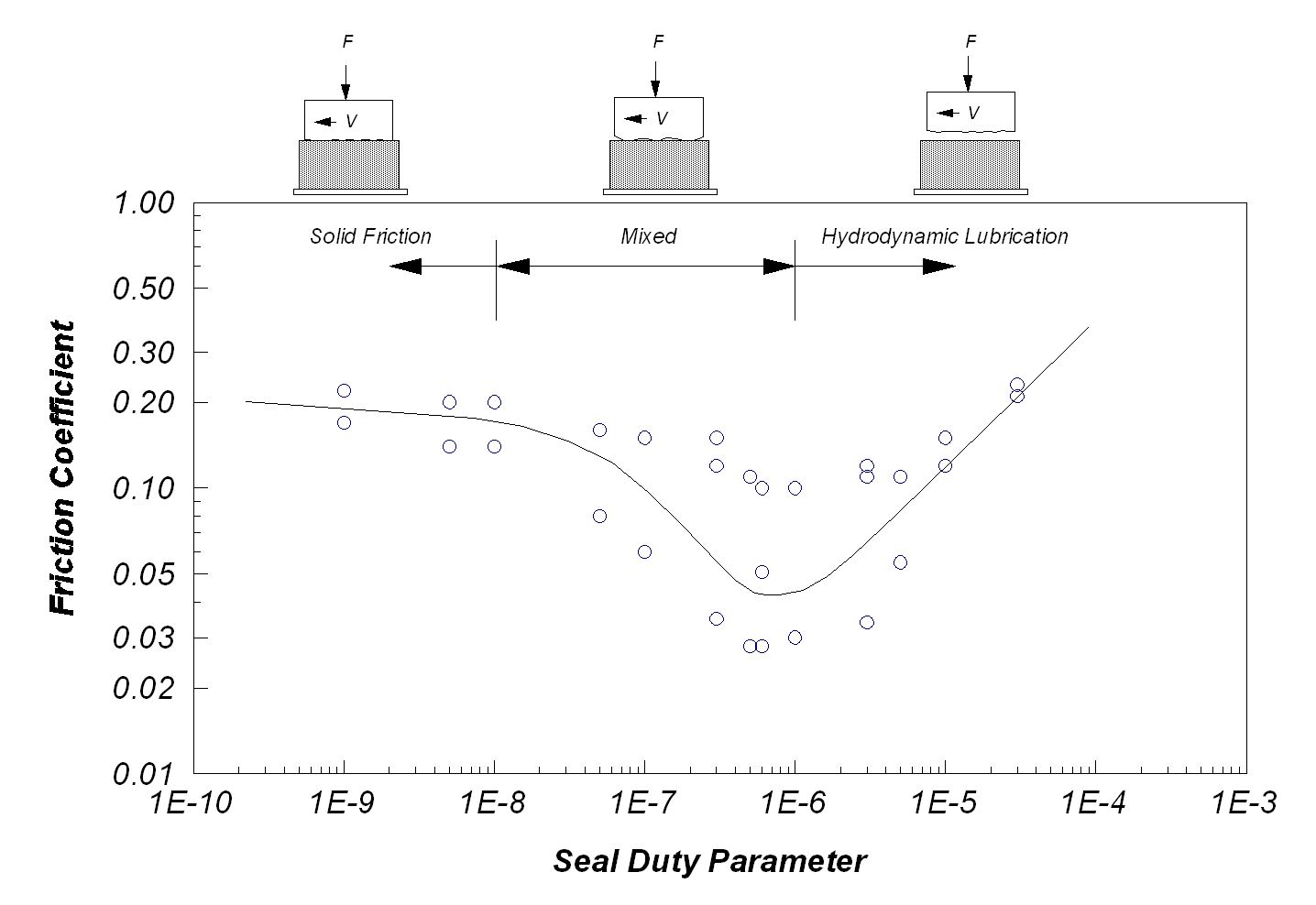
Examination of Figure 4 shows that hydrodynamic lubrication is considered to begin near a Seal Duty Parameter of 1×10⁻⁶. Mixed film lubrication begins near a Seal Duty Parameter of 1×10⁻⁸. Note that the coefficient of friction has its lowest values in the mixed lubrication regime but that there is a lot of scatter in the data.
Because of problems when “stick – slip” at the seal faces excites undamped vibration of the bellows or forces a lateral offset, the preferred application of metal bellows seals is in, or near, the hydrodynamic lubrication regime.