
Designing for Pressure
Whereas piping and pressure vessels are fixed equipment with ratings that can be well defined by structural limits, mechanical seals are dynamic with both structural limits and performance limits. In addition, the performance of the mechanical seal is dependent on the fluid that is being sealed and the operation of the equipment. The overall performance of the seal may even be time dependent as the physical properties of various components, especially elastomers, change during operation. Finally, performance of a seal is often path dependent; that is, the steady state performance depends on the startup conditions and procedure. Again, rating a mechanical seal is not a simple process.
Pressure Limits
API 682 defines three pressure terms that relate to the mechanical seal:
Maximum static sealing pressure is
Maximum dynamic sealing pressure is
Maximum allowable working pressure is
API 682 also defines the pressure casing as including the seal chamber but excluding the stationary and rotating members of the mechanical seal. This means that there is no requirement that the seal have the same maximum allowable working pressure as the pump. Obviously, but not stated, the seal is expected to have a static pressure rating equal to or exceeding the maximum static sealing pressure for that service. The seal obviously should have a dynamic pressure rating equal to or exceeding the maximum dynamic sealing pressure but this requirement is not stated.
These definitions establish the difference between static and hydrotest ratings. They also insure that performance is not affected by static conditions within the limits of the static sealing pressure rating. In many cases, the static rating will be equal to the hydrotest rating.
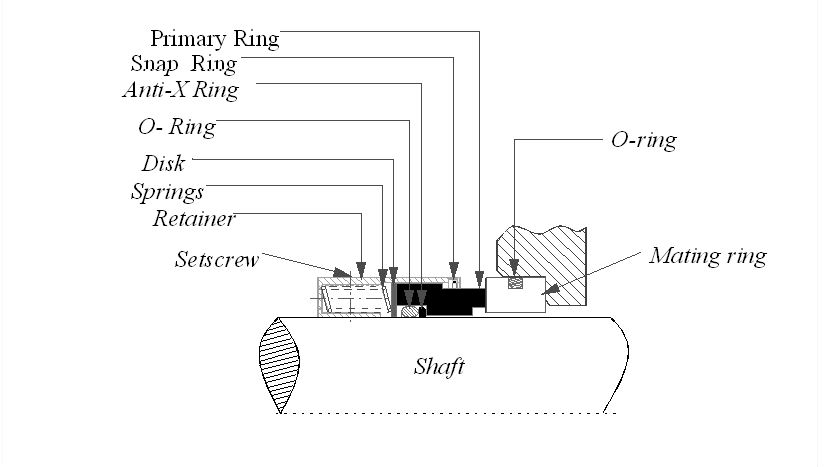
To illustrate the principals involved in rating a seal, a single, rotating pusher seal will be used. For simplicity, an unbalanced seal is shown in Figure 1. The primary ring is manufactured from a single piece of carbon graphite. The mating ring might typically be manufactured from silicon carbide or tungsten carbide.
Stresses
When the seal is pressurized, stresses are produced within the primary ring and mating ring. These stresses may be estimated by using the equations for stress in a cylinder. Equation (1) is the relationship for a thin wall cylinder and is used herein for purposes of illustration; however, using the relationships for a thick wall cylinder is more accurate.
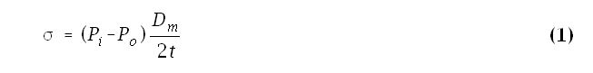
Equation (1) produces positive values, that is, tensile stresses, for internal pressurization and negative values, that is, compressive stresses, for external pressurization. These stresses must be compared to the tensile or compressive strength of the material. Carbon graphite is much weaker than either tungsten carbide or silicon carbide. Since these components are often roughly the same size, the carbon graphite primary ring is usually, but not necessarily, the limiting component with respect to pressure induced stresses.
As an example, suppose that the primary ring has a 4 inch mean diameter with 1/4 inch cross sectional wall thickness. Using Equation (1), the stress at, say, 1000 psi external pressure is 8,000 lbf/in2 in compression. This level of stress is well within the compressive strength of carbon graphite.
If, on the other hand, the same seal is pressurized internally, the stress is 8,000 lbf/in2 in tension. Carbon graphite , with a tensile strength of perhaps 7,000 lbf/in2, is not adequate for this pressure. A stronger carbon graphite (or perhaps another type of material) would be required. Alternatively, the wall thickness could be increased.
O-ring Extrusion
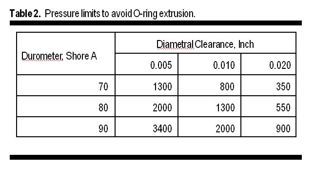
Many pusher seals use an O-ring or other elastomeric gasket as a secondary sealing element. Table 2 shows some of the guidelines and limitations when O-ring extrusion is considered. O-ring extrusion results in a degradation of seal performance and not a rupture. As such, consideration of O-ring extrusion should be included in the static and hydrotest ratings as well as the dynamic rating.. High durometer O-rings usually have more frictional drag and less flexibility than low durometer O-rings. Many high pressure seals and some general purpose seals use anti-extrusion rings to prevent extrusion while maintaining adequate clearance.
Dynamic Sealing Pressure Rating
When discussing dynamic ratings, the relationship between leakage and wear becomes particularly apparent. In mechanical seal technology, the classical, but simplistic approach to analysis of wear is by using the PV value.
PV Value
The PV value is widely used as a guideline for mechanical seal design and application.
 The PV value can be important because it represents both wear and heat generation. Even so, it has only a very rough correlation with overall seal performance. In Equation (2), the pressure gradient factor, k, is taken as ½. In actual service, the value for k may vary from 0 to 1. Nevertheless, it is convenient and the usual practice is to use k = ½ when dealing with PV calculations.
Industry practice has been to limit the PV value based on seal face material combinations and to attempt to couple this limit with fluid properties. For example, a typical limit is 500 kpsi ft/min for resin filled carbons versus tungsten carbide for seals in “non-lubricating” liquids in typical pump services. Higher values (usually by a factor of 1.6) are allowed for “lubricating” liquids. Table 3 gives some examples of the recommended maximum PV values for various material combinations.
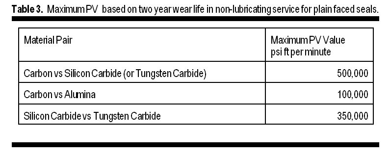
Table 3 is not meant to be an all-inclusive reference; it merely illustrates the concept and general order of magnitude of PV limits for a material pair. In working with PV limits, it is important to recognize the basis and limits of this concept. Much of the data is based on tests of a commercially available 3-3/8″ unbalanced seal at 1800 rpm in warm water. The tests are run for 100 hours and the wear is measured. The PV limit is defined by either excessive wear for the target design life or by damage due to some sort of “overload” — usually thermal in nature.
When PV limits are used as the basis for wear, it is important to recognize that the maximum recommended values are often based on a two year life with a 1/8″ wear length. This is 0.00071 inch wear during the 100 hour test — a difficult measurement to obtain accurately! If a longer wear life is required, then the PV limit must be lowered. If the available seal wear length is less than 1/8″ then either the PV limit must be lowered or a lesser wear life is projected. These are extreme extrapolations — a 17,520 hour wear life is projected from a 100 hour test! In the 100 hour test, most of the wear undoubtedly occurs during the first few hours of the test. In actual long term service, mechanical seals rarely wear out.