
Plan 66B, like Plan 66A, is a leakage detection system that was designed for single seal pipeline applications. Although Plan 66A is preferred, sometimes dimensional constraints prohibit its use and Plan 66B is then recommended.
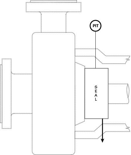
Plan 66B cannot be adequately described using only a schematic. In Plan 66B an orifice plug is installed in the gland drain connection which allows normal seal leakage to freely exit the drain port. If the seal leakage becomes excessive then the orifice plug limits the amount of leakage that can pass through the orifice and creates a back pressure on the upstream side of the orifice. The pressure increase will be sensed by the pressure transmitter and set off an alarm indicating a seal failure. Since the cavity between the seal and the bushing will become pressurized, a segmented throttle bushing must be used to limit the leakage past the bushing. The leakage from the drain connection is piped to a sump or to a liquid recovery system.
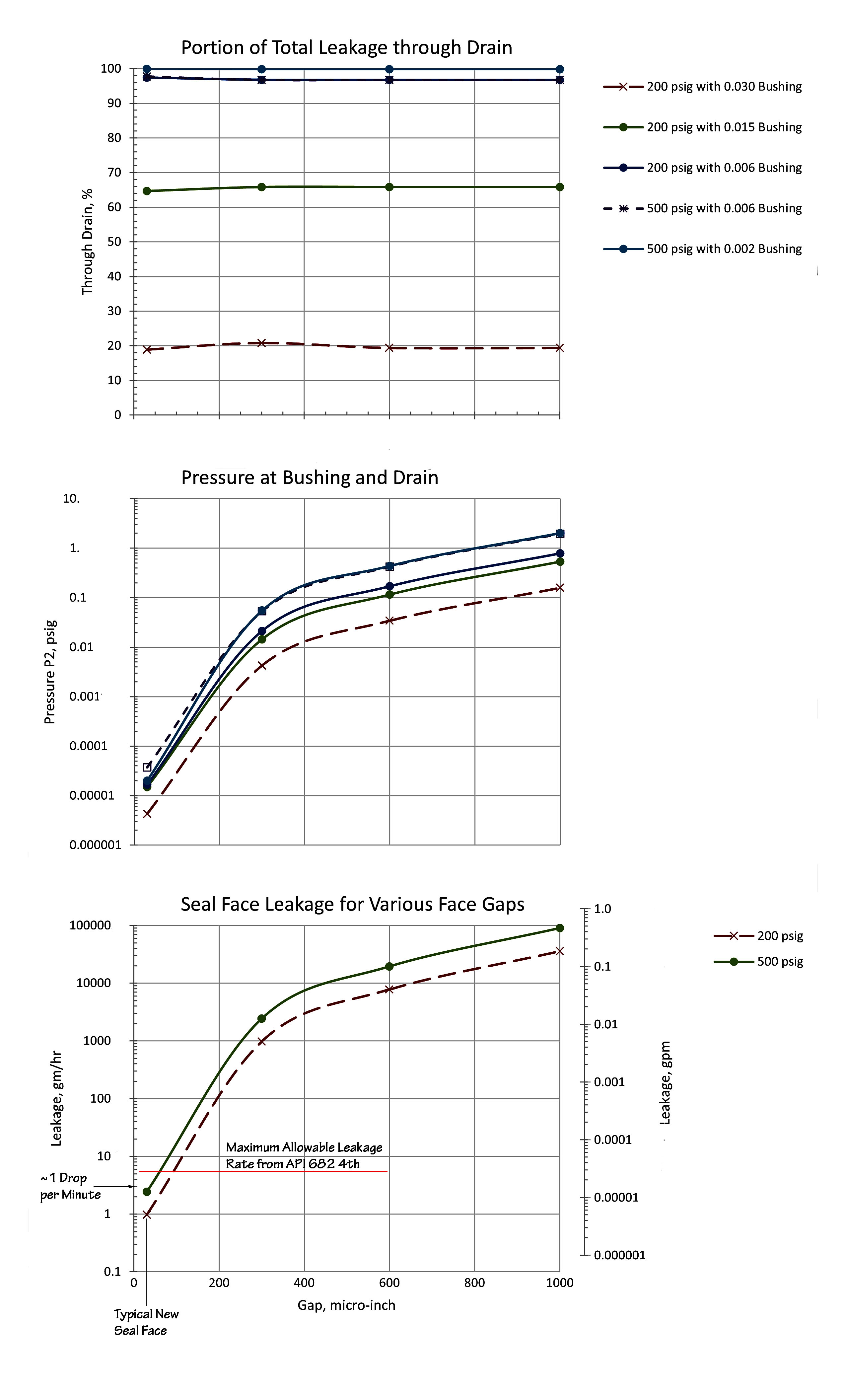
As will be shown in the following mathematical model, Plan 66B is not sufficiently sensitive to seal face leakage to be used for trending leakage rate. However, Plan 66B can be used to detect high seal face leakage rates.
Seal face leakage is from the seal chamber at pressure P1 to a drain pressure, P2. All seal face leakage must exit through either the throttle bushing or drain piping. Throttle bushing and drain leakage is from P2 to ambient pressure. The pressure P2 must be sufficiently high to force all the seal face leakage through the drain piping and bushing. Note that there is no flow through the pressure transmitter.
Example using Plan 66B
Suppose that, given the conditions shown above, a leakage rate of 3 gm/hr is acceptable but 30 gm/hr is not. Using Piping Plan 66B, what alarm pressure represents 30 gm/hr seal face leakage?
Answer: 0.00067 psig (details not shown)
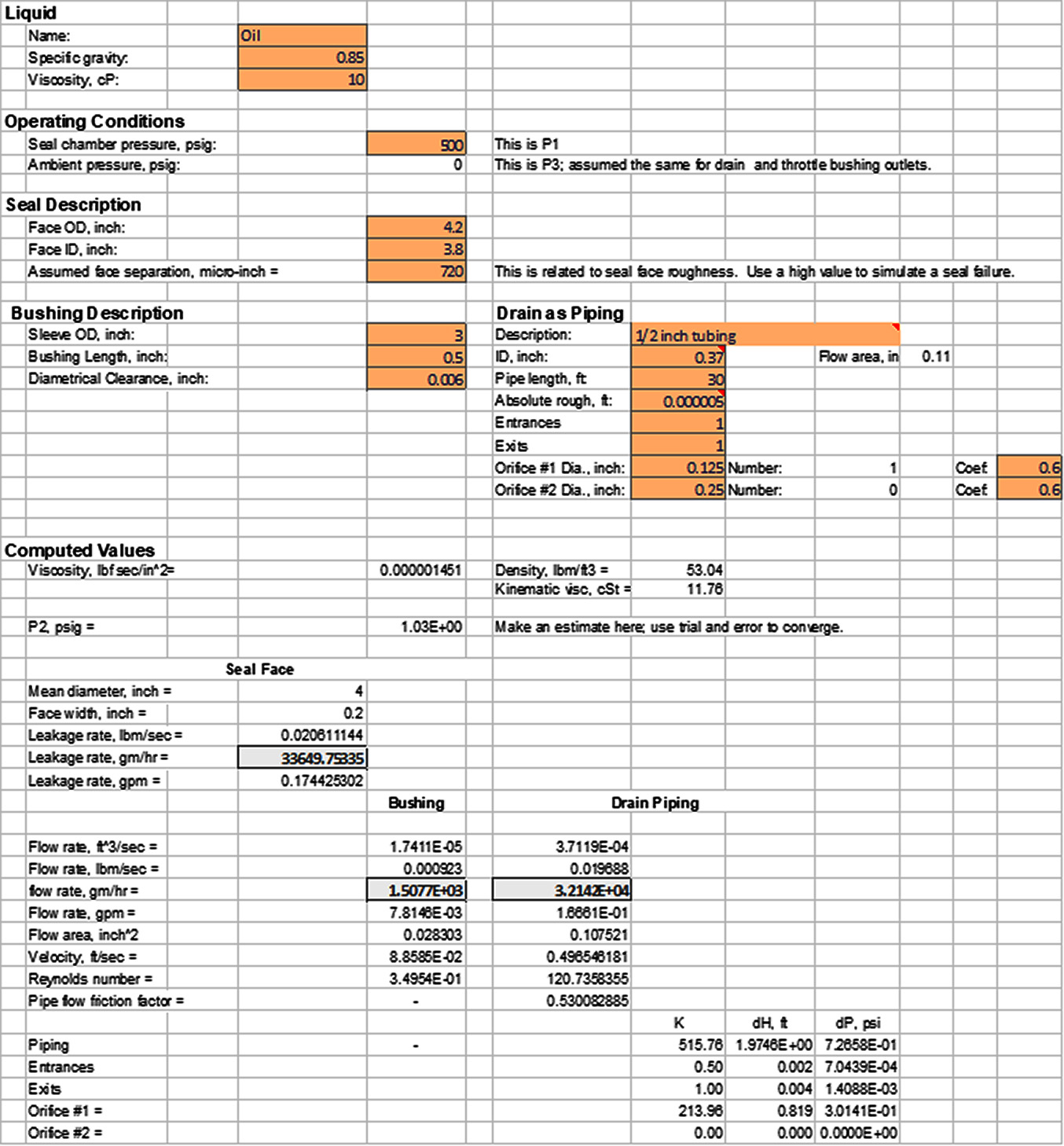
What seal face leakage rate will trigger a 1 psig alarm? What is the throttle bushing flowrate?
Answer: 33650 gm/hr (0.17 gpm) total leakage; 1508 gm/hr from the throttle bushing (details shown above).
Suppose that the throttle bushing clearance is 0.002 inch instead of 0.006 inch. What seal face leakage rate will trigger a 1 psig alarm? What is the throttle bushing flowrate?
Answer: 31726 gm/hr (0.16 gpm) total leakage; 55 gm/hr from the throttle bushing (details not shown).
The graph below is representative of the performance of Plan 66B when the orifice is 0.25 inch diameter.