
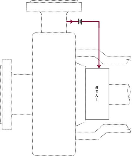
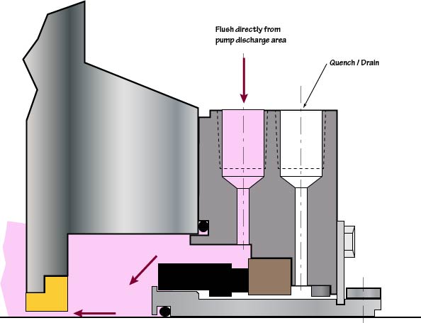
Plan 11 is by far the common piping plan; it is used in well over 50% – perhaps even 75% — of all seal applications. Plan 11, sometimes called “discharge bypass”, simply takes fluid from the discharge area of the pump (or the discharge of and intermediate stage if applicable) and routes it into the seal chamber. Plan 11 is often combined with other piping plans, especially with dual seals, for example Plan 11/52.
The flush flow rate is usually controlled by an orifice in the flush line. Orifices should not be less than 1/8 inch (3 mm) unless the product is very clean. Without an orifice, the restriction is usually the drilled hole in the gland plate and flow rates and impingement velocities can be quite high.
Flowrate through a 1/8″ orifice can be surprisingly high. With 100 psi differential pressure, flowrates range from 2 to 3 gpm. For a 3/16″ orifice, 100 psi can produce 5 to 7 gpm.
An interesting challenge arises when the differential pressure is high and a 1/8 inch orifice allows more flow than is desired. This can be addressed two ways. One option is to use two or more orifices in series. The number is dependent on the differential pressure. The other way is to use a “choke tube”. A choke tube is a piece of small diameter tubing. The length of the tubing is calculated using a piping pressure drop calculation such that the pressure drop across the tubing is equal to the difference between the discharge pressure and the seal chamber pressure at the desired flow rate. Choke tubes are not used very often.