
Heat Soak
Heat soak is defined as heat transfer from the solid seal chamber to the fluid within the seal chamber. Heat soak can be positive or negative; that is, heat soak can be from the seal chamber to the fluid within or from the fluid to the seal chamber. Typically, the term heat soak is used to describe the heat transfer from a hot pump into a cooler fluid inside the seal chamber.
Figure 1 illustrates the concept of heat soak. In Figure 1, the pump is hot but the seal chamber is cool; therefore there is heat transfer from the hot metal of the pump to the fluid within the seal chamber. Realistically, there are steep temperature gradients within the pump case, the seal chamber, the shaft and the fluid within the seal chamber. For purposes of estimating heat soak, these temperature gradients will be ignored.
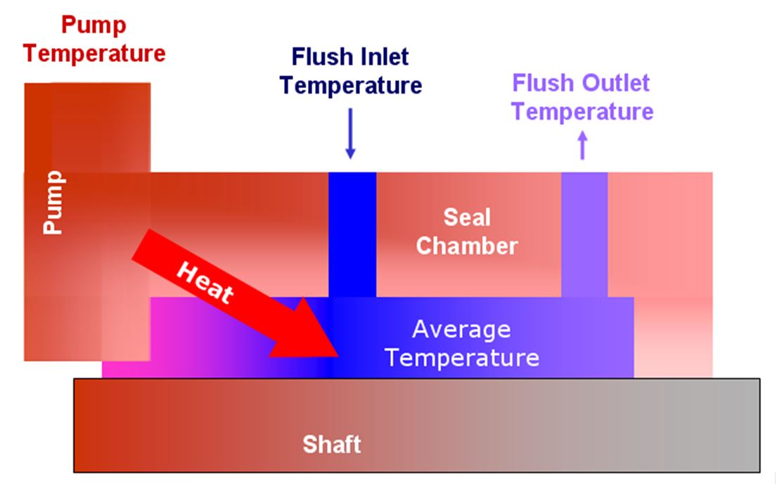
The heat soak process consists of both conduction and convection heat transfer. To get a mental picture of the heat soak process, imagine the situation in the seal chamber of a hot pump as shown in Figure 1. Heat is transferred by conduction from the hot pump case into the walls of the seal chamber. Cool fluid is circulated through the seal chamber and absorbs heat from the hot walls by convection. The pump shaft also is hot and contributes to heating the fluid. The fluid exits the seal chamber at a higher temperature than its inlet temperature. At the same time, the fluid is cooling the walls of the seal chamber as well as the pump shaft. The amount of heat (energy) absorbed by the fluid is equal to the amount lost by the seal chamber and pump shaft.
Although Figure 1 shows a hot pump with a cool fluid in the seal chamber; the inverse could also be true: a hot fluid inside the seal chamber of a cold pump.
Heat soak also takes place to/from the buffer/barrier fluid chamber of dual seals.
Heat Soak Calculations
API 682 Method
The API 682 equation for estimating heat soak is in the form of
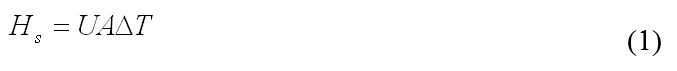
In Equation 1,
Hs = heat soak, Btu/hr
UA = 12S where S is the seal size in inches
ΔT = pump temperature – seal chamber temperature, °F
The “UA” value should be based on tests of the specific pump and/or seal chamber. That is, the pump manufacturers and seal chamber manufacturers should provide the UA value. The suggested relationship, UA = 12S, produces a rough approximation of a chart provided to the API by the Durametallic (now Flowserve).
For widespread use of Equation 1, it is more appropriate to use the mean face diameter of the seal instead of the seal size. This convention (mean face diameter) will be used throughout the remainder of this report.
Equation 1 is intended to be an estimate and used only in the absence of data. It seems to be approximately representative of the actual heat soak, especially for API 682 seals in water at shaft speeds of 1800 rpm. For oils and for slower shaft speeds, Equation 1 probably predicts a high value for heat soak.
Example
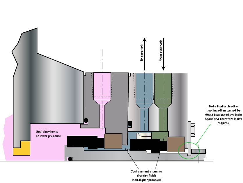
A 3.5 inch high temperature pressurized dual seal, see Figure 2, is to be used in a 500 °F pump at 3600 rpm. A reservoir bulk temperature of 150 °F is the goal/design target. What is the heat soak to the barrier fluid?
The heat soak can be estimated from Equation 1. If the bulk temperature of the barrier fluid is 150 °F and the pump temperature is 500 °F, then the heat soak is
Hs = 12 (3.5) (500 – 150)
Hs = 14700 Btu/hr
Remember that the total heat load on the reservoir is the heat load from the seals plus the heat soak.
Improvements to the API Equation
The heat soak estimates can be improved by making slight modifications to the API 682 heat soak equation as follows:
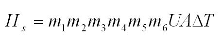 where
where
Hs = heat soak, Btu/hr
UA = the API default of 12S where S is the seal size in inches
ΔT = pump temperature – seal chamber temperature, °F
m1 = speed factor, (rpm/1800)0.26 , for example
= 1.0 for 1800 rpm (base case)
= 1.2 for 3600 rpm
= 0.90 for 1200 rpm
m2 = thermal conductivity factor
= 1.0 for stainless steel (base case)
= 2.3 for carbon steel and cast iron
= 1.4 for 12% chrome steel
m3 = thickness factor
= 1 for 1 inch thick seal chamber wall (base case)
= 0.81 for 0.5 inch thick seal chamber wall
= 1.13 for 1.5 inch thick seal chamber wall
= 1.24 for 2.0 inch thick seal chamber wall
m4 = bore factor, (seal chamber bore/API bore)
= 1.0 minimum
= 1.0 for API 610 standard bore and seal sizes
m5 = viscosity factor, (.4/u)0.15 , for example
= 1.0 for 0.4 cP (base case)
= 1.11 for 0.2 cP
= 0.87 for 1 cP
= 0.68 for 5 cP
= 0.62 for 10 cP
m6 = combined fluid properties factor excluding viscosity
= 1 for water (base case)
= 0.78 for synthetic oil barrier fluids
= 0.72 for conventional lube oils
= 0.65 for non-vaporizing hydrocarbon mixtures
= 0.53 for vaporizing hydrocarbon mixtures
Extension of Example
The improved heat soak equation will now be applied to the previous example. Suppose the shaft speed is 3600 rpm; the viscosity of the barrier fluid is 5 cP at the target temperature of 150 °F. The seal chamber is stainless steel and the walls are 1.5 inches thick. Consider the various multiplier factors and obtain an improved estimate for heat soak.
- For 3600 rpm, m1 = 1.2
- For stainless steel, m2 = 1.0
- For 1.5 inch wall thickness, m3 = 1.13
- For the API dimensional envelope, m4 = 1.0
- For viscosity of 5 cP, m5 = 0.68
- For synthetic barrier fluids, m6 = 0.78
The product of all these factors is 0.719; therefore an improved heat soak estimate is
Hs = (0.719)(14700)
Hs = 10569 Btu/hr