
Designing and Using Pumping Rings
Pumping rings are internal pumps used inside centrifugal pumps to promote flow in various closed loop circulation systems. Several different types of pumping rings are available.
Introduction
Seals generate heat. Usually a fluid flush is used to control the fluid temperature. The most common flush method uses a simple injection of the fluid; flow is controlled by the differential pressure between the source and seal chamber. API flush Plan 11 is a good example of injection. In contrast, some flush methods circulate fluid through a closed loop system. This is especially common for multiple seal arrangements. Examples of closed loop systems include API Plans 23, 52 and 53.
In these closed loop systems, flow may be produced by either thermal or rotational effects. Flow produced by thermal effects is called thermal siphon, thermo-siphon or thermal convection flow. Flow produced by rotational effects is considered to be mechanically induced as though by a pump. This pumping may be produced by either axial flow and/or radial flow devices. All of these devices are usually described as pumping rings although API 682 uses the term “internal circulation device“. Axial flow pumping rings are sometimes called scrolls.
Frequently, systems are classified as thermal siphon systems simply because there is no separate component that can be labelled as a pumping ring. However, the lack of a pumping ring does not necessary mean that circulation is produced solely by thermal effects. It is possible to produce a significant flow by using only the rotating seal head or even the shaft to produce the pumping effect. Also, the presence of a pumping ring does not necessarily guarantee that sufficient fluid is being circulated to provide the desired amount of cooling.
Flow Requirements
Flow guidelines for pumping rings are generally based on the same guidelines as for recommended flush rates.
Pumping Ring Types
Any of the various built-in circulating devices that produce flow for mechanical seal systems are usually described as pumping rings. Common designs include:
- radial flow impellers using drilled vanes
- radial flow using slots
- axial flow using spiral grooves
Any of these designs can produce good flow rates. In fact, it sometimes seems that only the diameter and shaft speed are important. To a certain degree, this is true; however, pumping ring performance can vary significantly with certain design parameters. After a brief discussion of pumping ring types and details, there is a section on good design practices.
Radial Flow Pumping Ring using Vanes
A vaned radial flow pumping ring looks like a enclosed centrifugal pump impeller except that the vanes are replaced by straight, drilled holes. Figure 1 shows a drilled vane radial flow pumping ring. Usually the inlet and outlet gland ports for the pumping ring flow are perpendicular to the axis of the pumping ring. The flow into the pumping ring eye is axially directed but the outlet is perpendicular to the axis. Even though a cross sectional view may indicate that the outlet flow is radially directed, there is a component tangential to the pumping ring outside diameter. This tangential component is the reason pumping ring performance is so much better when the outlet porting is also tangential.
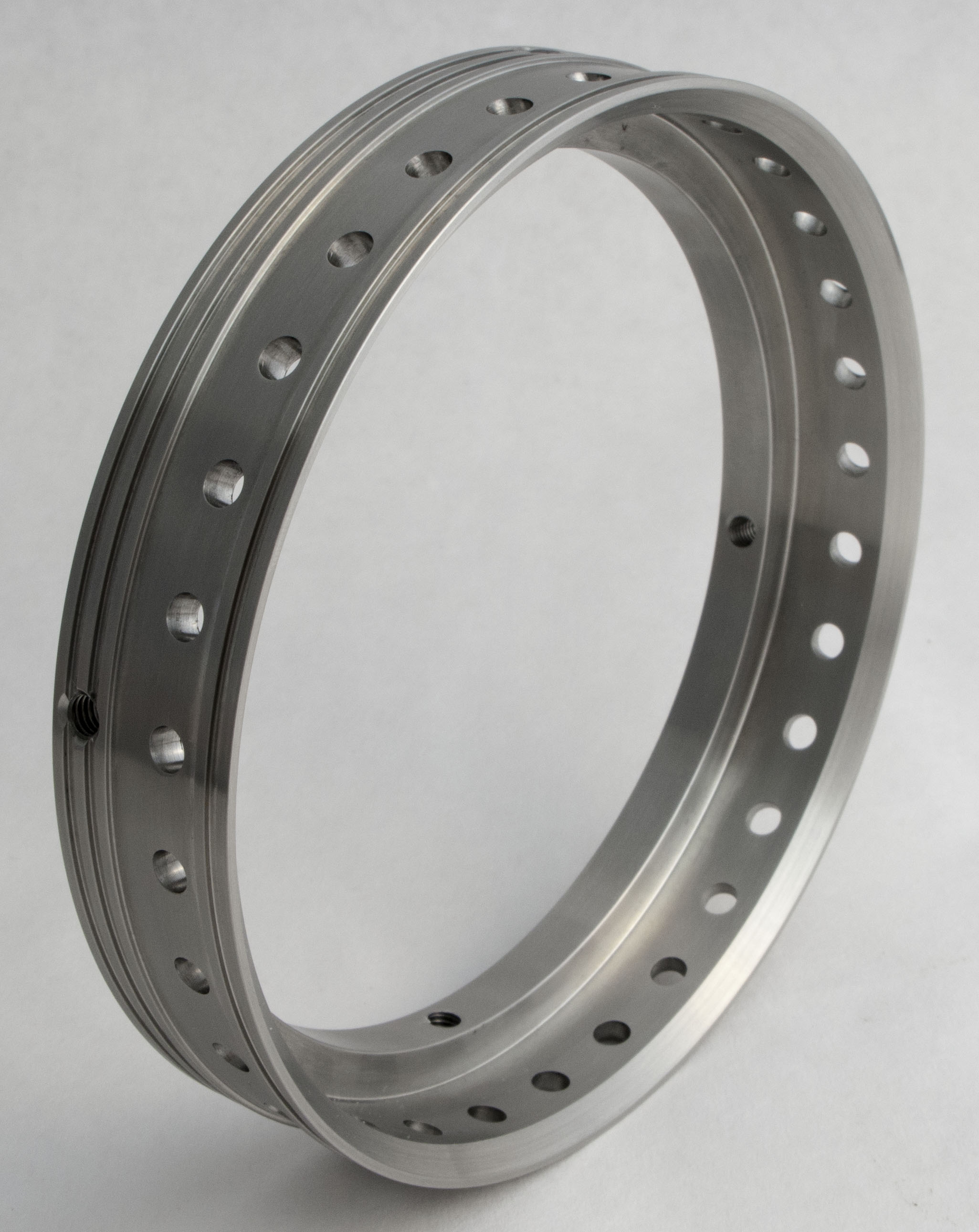
Figure 2 illustrates the concept of the tangential outlet. In Figure 2, the shaft is rotating counter-clockwise in a circular case. The shaft is surrounded by fluid. The outlet port in the case is oriented to be tangential to the outside diameter of the shaft. The arrows represent the path of the surrounding fluid as it is given velocity and direction by the rotation of the shaft.
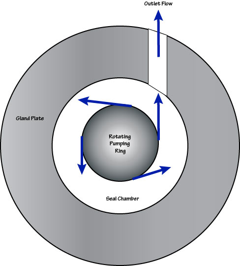
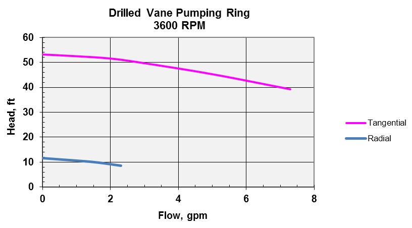
Figure 3 shows the performance curve for a drilled vane radial flow pumping ring. This performance curve is for an OD of 5.5″ with radial clearance approximately 1/16″. The outlet port was through drilled to 1/2″. This curve is based on tests conducted on water. The drilled vane pumping ring can be a very good performer but manufacturing it is more difficult than for some of the other types. Also, for best performance, the drilled vane pumping ring requires more radial and axial space than does some other types. Notice that performance with tangential outlet is considerably better than with radial outlet; however, this is true for all pumping ring types.
Radial Flow Pumping Ring using Slots
A through slotted radial flow pumping ring looks like an open centrifugal pump impeller except that the vanes are straight slots. This is a relatively simple design to manufacture. Figure 4 shows a cross section of a through slotted radial flow pumping ring. Like the drilled vaned pumping ring, performance is best when the outlet port is tangential to the outside diameter of the pumping ring.
Unfortunately, slotted designs are usually used when both radial and axial space is very limited so the overall perception is that its pumping rate is less than a similar sized vaned pumping ring.
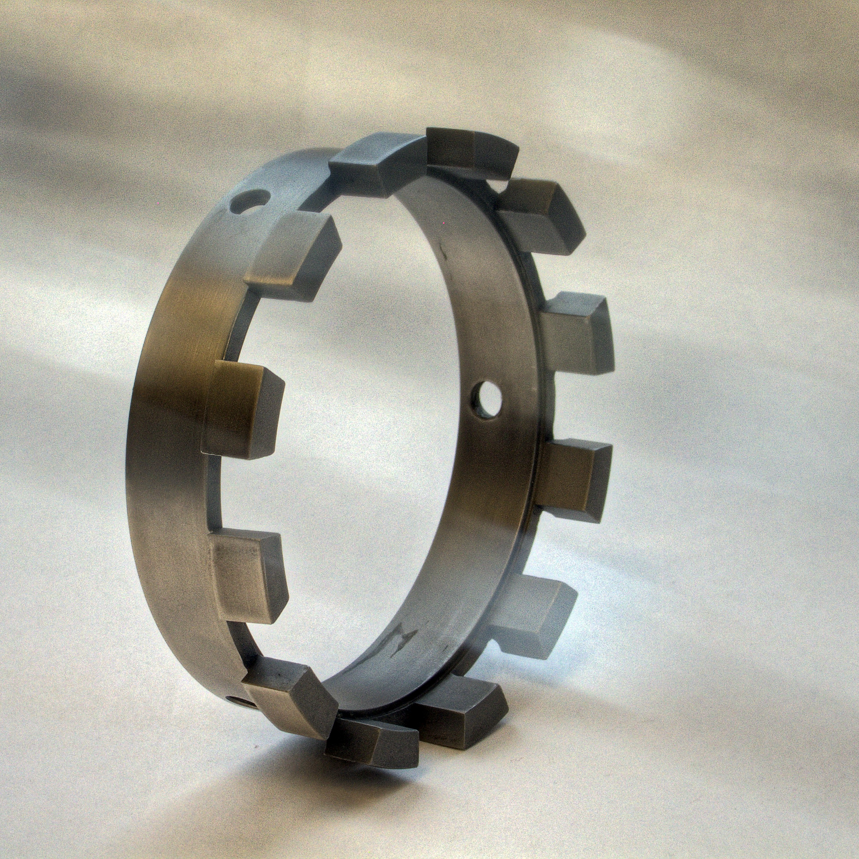
Figure 5 shows a variation of the slotted design which uses partial slots. Sometimes this design is called a “paddle-wheel”.
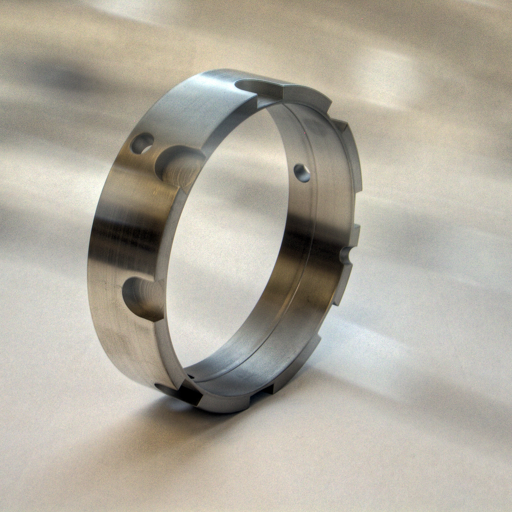
Figure 6 shows performance of a partially slotted pumping ring of about 5-1/2″ diameter at 3600 rpm and 1800 rpm when pumping water. The tangential outlet was 5/8″ drill through. Notice that
- developed head is much less than for the drilled vane impeller
- developed head and flow decreases markedly at 1800 rpm.
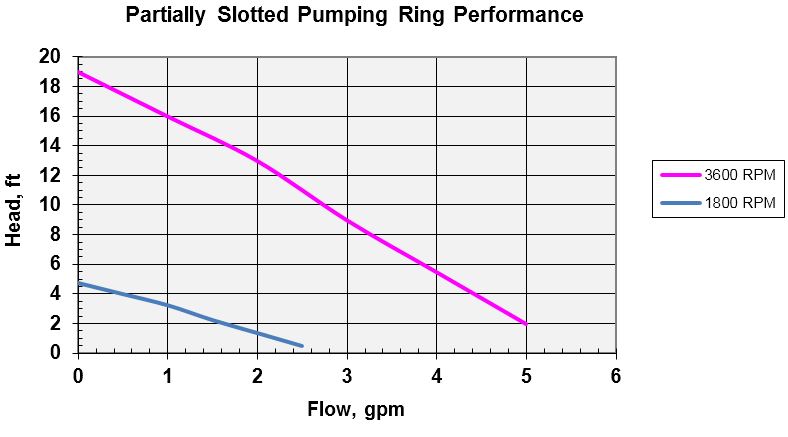
For all pumping ring designs, performance varies significantly with rotational speed. In fact, pumping ring performance at various speeds (as well as diameters) can be estimated by using the Affinity Laws for centrifugal pumps.
Axial Flow
An axial flow pumping ring looks somewhat like a screw or a rotating threaded sleeve; however, the threads are not typical screw threads. The threads must be matched to the direction of shaft rotation so that the fluid is pumped in the proper direction. Figure 7 shows an axial flow pumping ring.
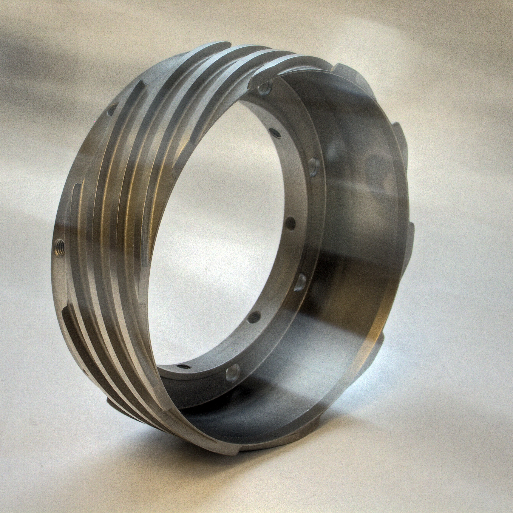
It is very important to realize that the flow from an axial flow pumping ring is axial in nature. Flow goes from one end of the ring to the other. Usually the inlet and outlet ports are perpendicular, not tangential, to the axis of the pumping ring; however, a tangential outlet (not inlet) is beneficial. Both inlet and outlet ports should lie completely outside the pumping vanes. If the inlet and outlet ports are over the vanes, the pumping rate may be severely reduced. In Figure 8, both good and bad practices are illustrated. The inlet port in Figure 8 is directly over the rotating vanes; this is a poor inlet design because centrifugal force will actually resist the flow into the pumping ring. The outlet port is properly located at the end of the pumping ring. For lack of a better guide, the recommended practice is that the centerlines of the ports should at least be aligned with the ends of the pumping ring. This is considered to be the maximum allowable overlap.
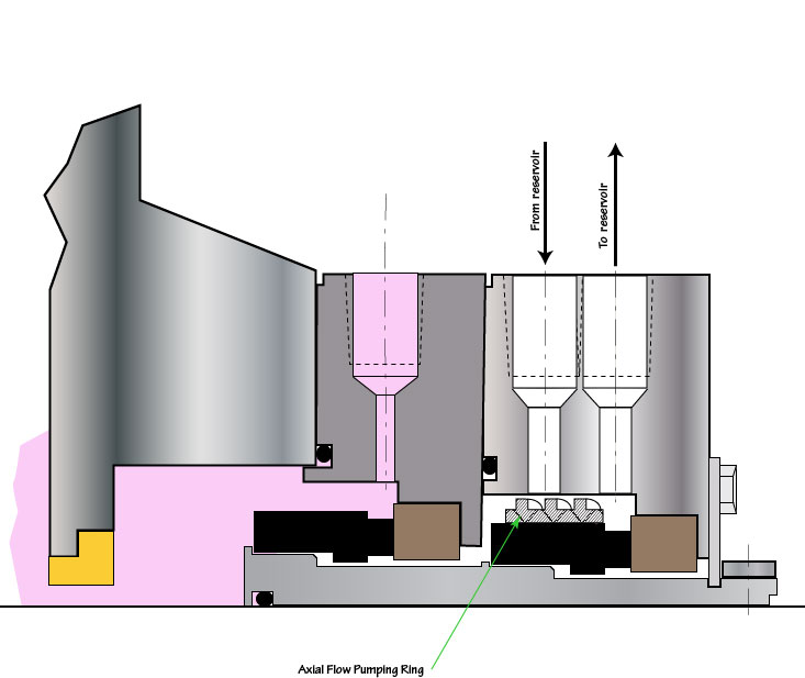
Figure 9 shows the performance curve for an axial flow pumping ring. Again, the performance curve has been normalized for a 5.5″ OD pumping ring. The curve in Figure 9 is for a radial outlet; a tangential outlet would have improved performance but sometimes cannot be fitted into the available space.
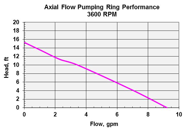
Axial flow pumping rings generally have better performance on oils than do the drilled vane or slotted designs.
Although it may seem strange, performance of axial flow pumping rings at various speeds can also be estimated by using the Affinity Laws.
Inlet and Outlet Ports
With respect to the inlet and outlet ports, all types of pumping rings benefit from the following guidelines:
- large ports
- radial inlet port
- tangential outlet port
- inlet port should be located over a diameter smaller than the pumping ring OD.
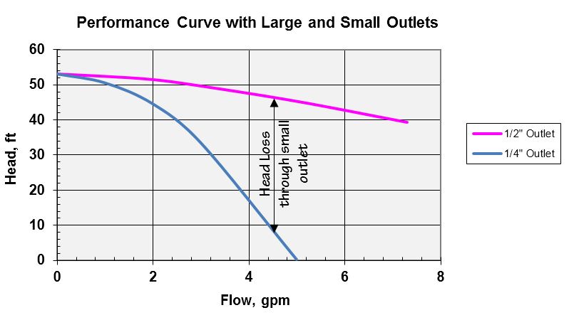
Performance curves are typically generated on a test rig having generous volumes and large ports but sometimes the available field dimensions force smaller ports. Small ports can have a drastic effect on the performance of the pumping ring.
Although not exact, the following procedure will produce a somewhat representative performance curve for a pumping ring having small ports:
- Obtain the performance curve based on large ports
- Imagine an orifice in the discharge piping
- The large port performance curve pressure is the inlet to the orifice
- The actual (small port) pressure is the outlet from the orifice
- For several flow points on the large port curve, compute the pressure loss through the orifice
- Subtract the orifice pressure loss from the large port performance curve.
An example of the effect of reduced outlet port size is shown below in Figure 10. Performance with 1/2″ outlet port is the drilled vane impeller of Figure 3.
Clearances
Although there is a widespread belief that small clearances between the pumping ring and seal chamber bore promote flow, this is not necessarily true. The optimal clearance is a function of many design parameters and can vary with the pumping ring design specifics. However, reasonable starting points for radial clearance generally fall in the range of 1/32″ to as high as 1/8″. API 682 guidelines for minimum pumping ring clearances are reasonable and vary with shaft size.
Affinity Laws
For pumping rings, the same Affinity Laws used for centrifugal pumps may be used to predict performance with respect to speed. In terms of speed, the Affinity Laws are
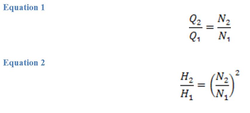
In Equations 1 and 2, Q is the flow rate and H is the total differential head. Any consistent set of units may be used. The procedure is to select a few representative points from the original curve and compute the points for the new curve by applying Equation 1 to the flow and Equation 2 to the head.
Summary of Good Design Practices
The following design practices have been proven to produce good pumping ring performance:
- Mechanical surface to impel flow (vane, slot, etc.)
- Smooth flow path into and out of the pumping ring
- Tangential exit flow path
- Radial inlet flow path (avoids pre-rotation)
- Large ports (drill throughs)
- Inlet flow path onto a smaller diameter
- Exit flow path from a larger diameter
- Clearances approximately like API 682 4th Edition