Leakage detection and management is a major consideration in the application of mechanical seals. Some arrangements and configurations can be fitted with drain connections and a throttle bushing to force leakage through that drain. Leakage through the throttle bushing remains near the gland plate whereas leakage through the drain can be piped away from the seal/pump. Piping Plans 65A/B and 66A/B are special piping plans for leakage detection and management but a simple run of pipe connected to the drain can also be used to route leakage to a disposal area.
An open drain means that all leakage will remain near the seal/pump. A plugged drain means that all leakage will go through the throttle bushing and remain near the seal/pump. Even a close clearance throttle bushing has little effect on reducing seal face leakage.
How large should the drain be in relation to the throttle bushing clearance? API 682 4th Edition provides some guidance. Fixed throttle bushings have a diametral clearance ranging from 0.025 to 0.040 inch. Floating carbon bushings have a diametral clearance ranging from 0.007 to 0.011 inch. A segmented variation of the floating carbon bushing typically rubs the sleeve slightly but performs as though the diametral clearance was 0.001 to 0.002 inch. The drain connection is typically 3/8” NPT but the drill through to the connection is more like 1/4” or 3/8” diameter. Piping Plan 66B uses either a 0.0625 or 0.125 inch diameter drilled hole in a plug placed in the drain connection.
Following is a simplistic procedure for estimating leakage rate and distribution to the drain and throttle bushing.
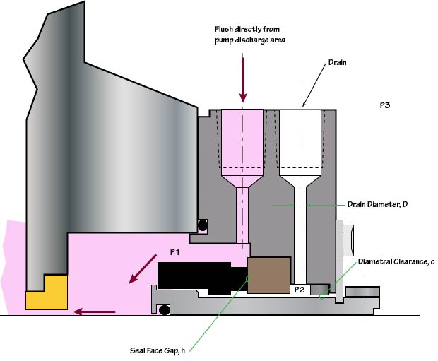
As shown in the figure above1, seal face leakage is from P1 to P2. All seal face leakage must exit through either the throttle bushing or drain piping. Throttle bushing and drain leakage is from P2 to P3. The pressure P2 must be sufficiently high to force all the seal face leakage through the drain piping and bushing. An increase in P2 also means a decrease (typically negligibly small) in seal face leakage.
There is no closed form algebraic solution for the analysis of this problem. However, by combining simple equations for seal face leakage, throttle bushing leakage and pipe flow, a trial and error approach can be developed to approximate the various flows. First, an estimate is made for P2. Using this estimated P2, seal face leakage can be determined. Next the flow through the drain piping is determined based on P2. Flow through the bushing is also calculated based on P2. The sum of the drain and bushing flows must equal the seal face leakage otherwise a new estimate is made for P2. This trial and error procedure is repeated until convergence is obtained.
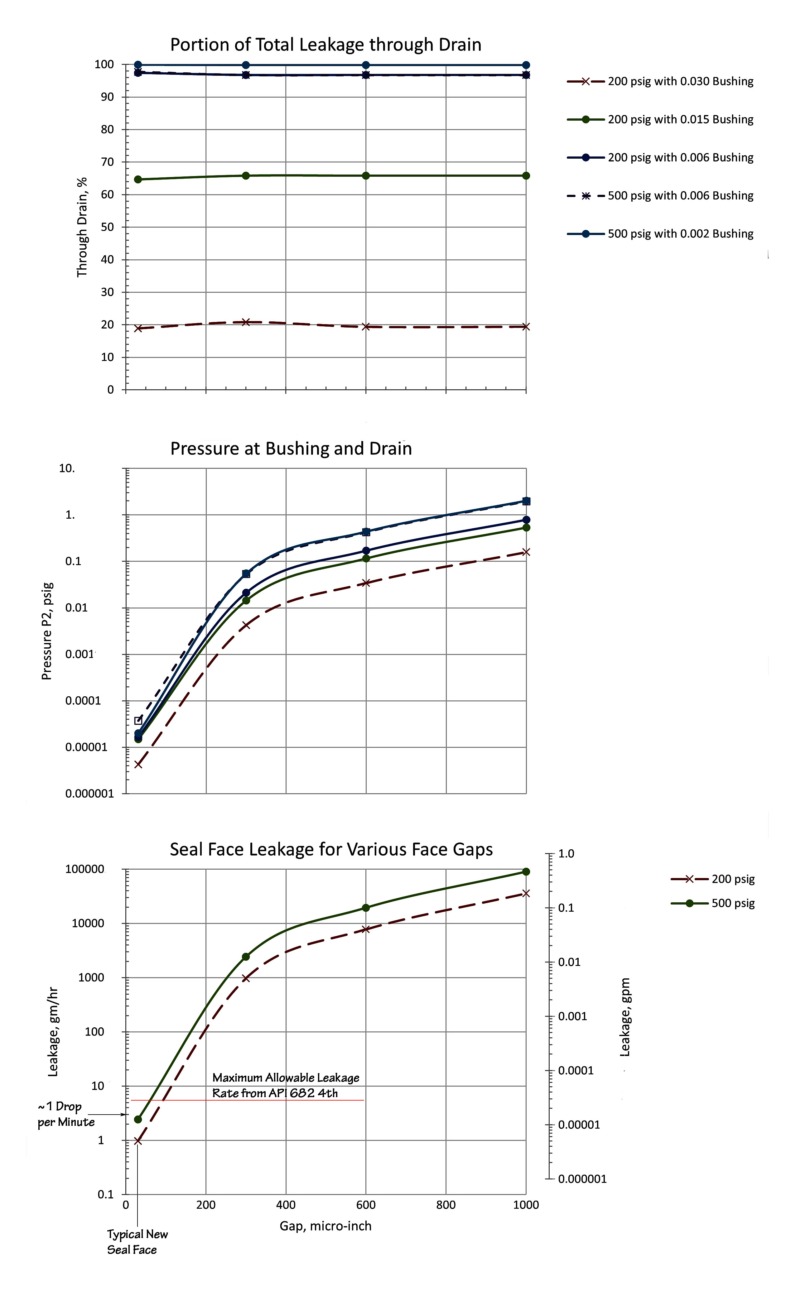
A number of trial cases were established and solved to get a feeling for the procedure and results. It quickly became apparent that as the throttle bushing clearance is reduced, almost all seal face leakage goes through the drain. Of course, it is the throttle bushing that forces flow to the drain and large throttle bushing clearances render the bushing less effective.
The same equations and procedures could be applied to Piping Plan 66B even though the illustration for Piping Plan 66B. For more information and details, see Piping Plan 66B.
Analysis of Plan 66A is slightly different because of the dual throttle bushings. For more information and details, see Piping Plan 66A.
The following conclusions may be drawn from this study:
- Except for very high seal face leakage rates in designs using fixed bushings, virtually all seal face leakage is routed through the drain connection.
- Floating or segmented throttle bushings (that is, not fixed bushings) should be used in Piping Plan 66A&B and the alarm pressure probably should be set to less than 1 psig.
- Piping Plans 66A&B are suitable for detecting sudden large leakage rates but not monitoring leakage trends.
- Piping Plan 66A is much more sensitive to leakage rates than Plan 66B.
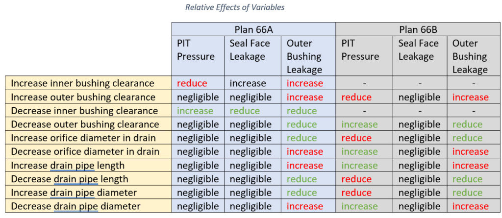
- Within the recommendations of API 682 4th Edition, the size of the drain piping, drain orifices and the clearance of the throttle bushing produce the trends shown in Table 1. Note that leakage from the outer bushing becomes environmental leakage at the pump unless drain piping is provided. The relative effects shown in Table 1 increase with increased seal face leakage rate.