A mechanical seal performs best when used in a clean environment of cool lubricating fluid. The exact requirements of clean, cool and lubricating vary with the design and materials of the mechanical seal. For non-optimum conditions, piping plans provide a means of adjusting the seal environment.
Since seal piping plans were developed, maintained and revised by the API, it would seem appropriate to include piping plans under the API 682 menu. However, piping plans are so important that having a dedicated menu seems more appropriate.
Piping plans and their names/labels date back to the early ’60s and the pump standard API 610. Piping plans described and discussed herein are based on API 682 4th Edition, Annex G. Piping plans are listed in numerical order below with links to the appropriate page on SealFAQs.
- Plan 01 Internal recirculation from pump discharge
- Plan 02 Dead-ended (no circulation)
- Plan 03 Circulation created by seal chamber design
- Plan 11 Bypass from discharge
- Plan 12 Bypass from discharge through strainer
- Plan 13 Recirculation from seal chamber to pump suction
- Plan 14 Bypass from discharge to seal and back to suction
- Plan 21 Bypass from discharge through cooler
- Plan 22 Bypass from discharge through strainer and cooler
- Plan 23 Recirculation from seal chamber through cooler and back to seal chamber using pumping ring
- Plan 31 Bypass from discharge through cyclone separator
- Plan 32 Injection from external source to seal chamber
- Plan 41 Bypass from discharge through cyclone separator and cooler
- Plan 51 Dead-ended atmospheric quench
- Plan 52 Unpressurized external reservoir with forced circulation by pumping ring
- Plan 53A Pressurized external reservoir with forced circulation by pumping ring
- Plan 53B Pressurized external bladder type reservoir with forced circulation by pumping ring.
- Plan 53C Pressurized external piston type reservoir with forced circulation by pumping ring.
- Plan 54 Circulation of pressurized barrier fluid from external system.
- Plan 55 Circulation of unpressurized buffer fluid from external system.
- Plan 61 Tapped connections only.
- Plan 62 Quench fluid from external source.
- Plan 65A Atmospheric leakage collection and detection system for single seals.
- Plan 66A Atmospheric leakage collection and detection system for single seals.
- Plan 66B Atmospheric leakage detection for single seals.
- Plan 71 Tapped connections only.
- Plan 72 External buffer gas purge for secondary containment seals.
- Plan 74 Pressurized external barrier gas for dual gas seals.
- Plan 75 Secondary containment drain for condensing leakage.
- Plan 76 Secondary containment drain for non-condensing leakage.
- Plan 99 Undefined – drawing or sketch is required.
Organization of the Piping Plans
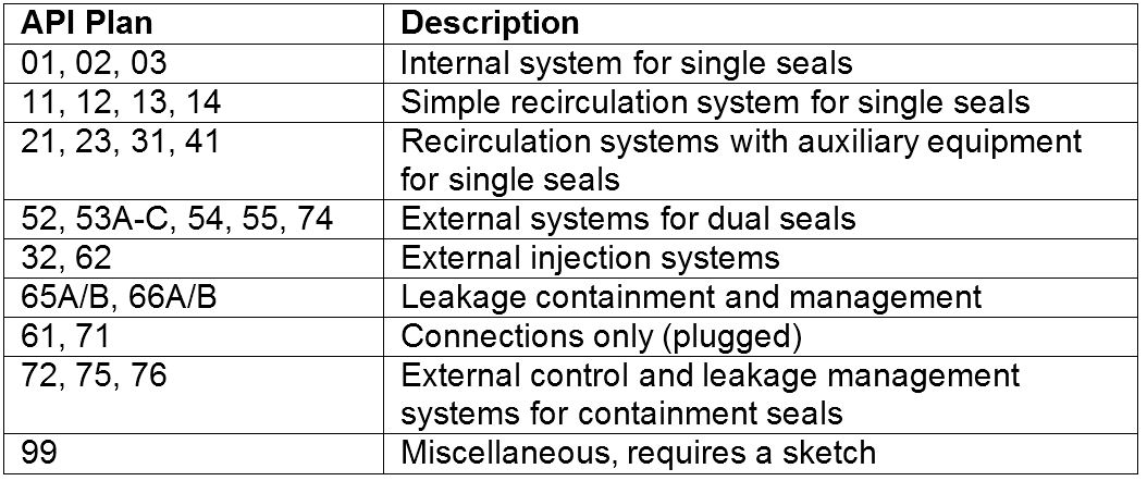
The various piping plans can be grouped in various ways. One method to group those plans having similarities in advantages / disadvantages, sizing of the system and system controls as shown below.
Piping Connections
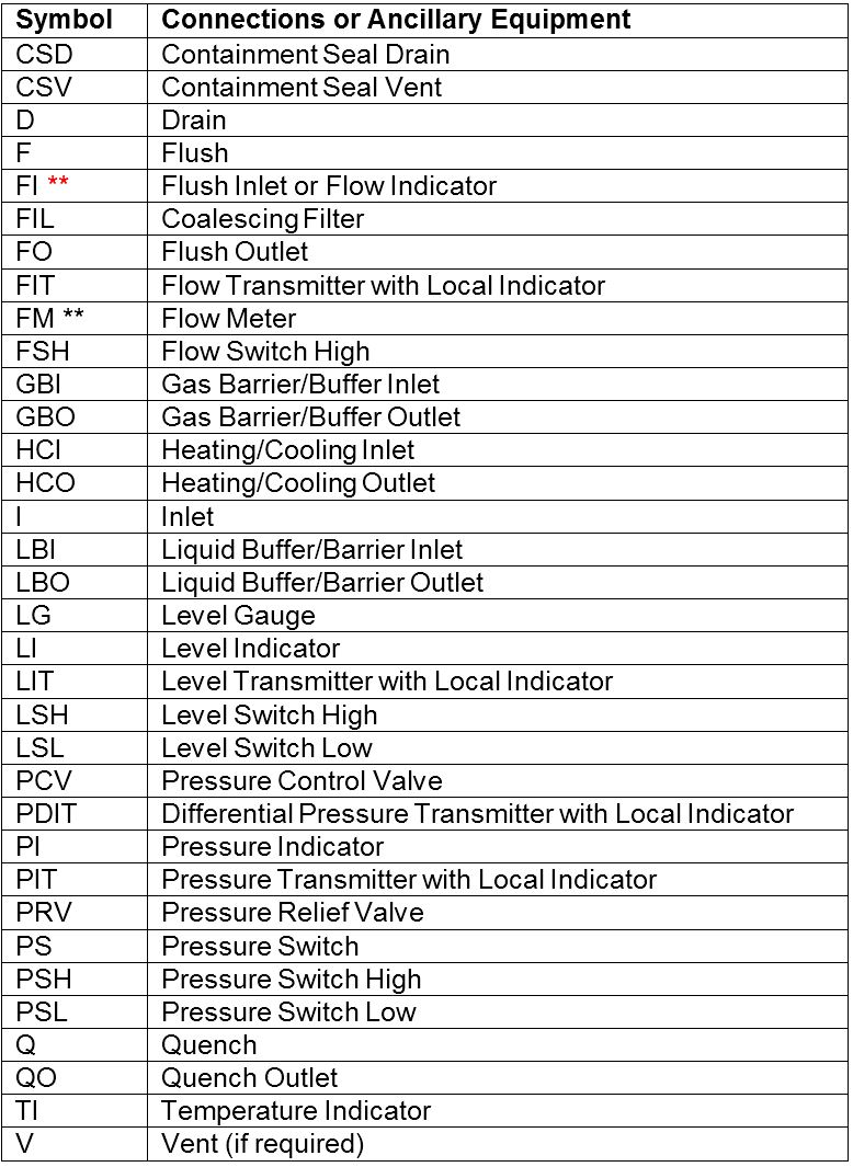
Piping must be properly connected. As an aid in reading, API 682 4th edition uses the following symbols in the piping plan schematics.
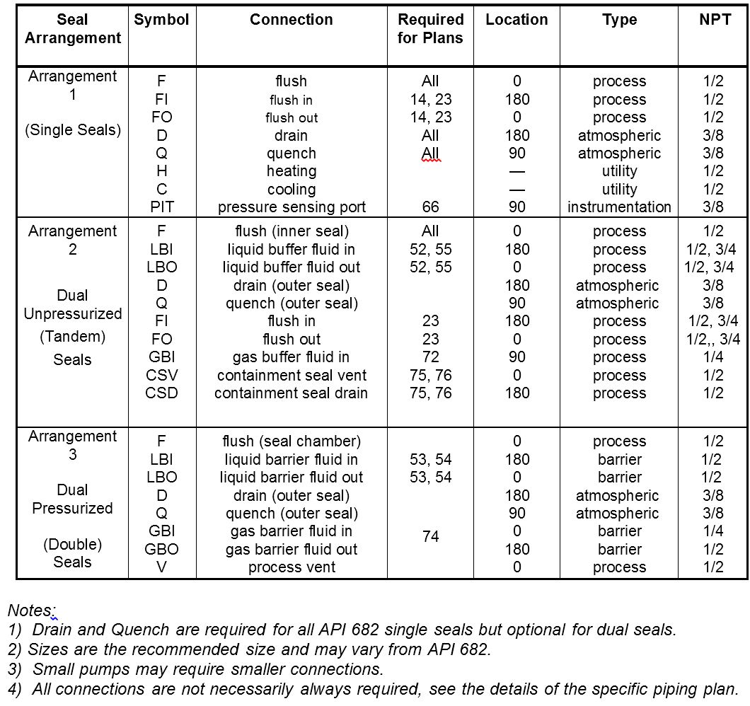
Seal chamber and gland plate connections should be marked as follows.
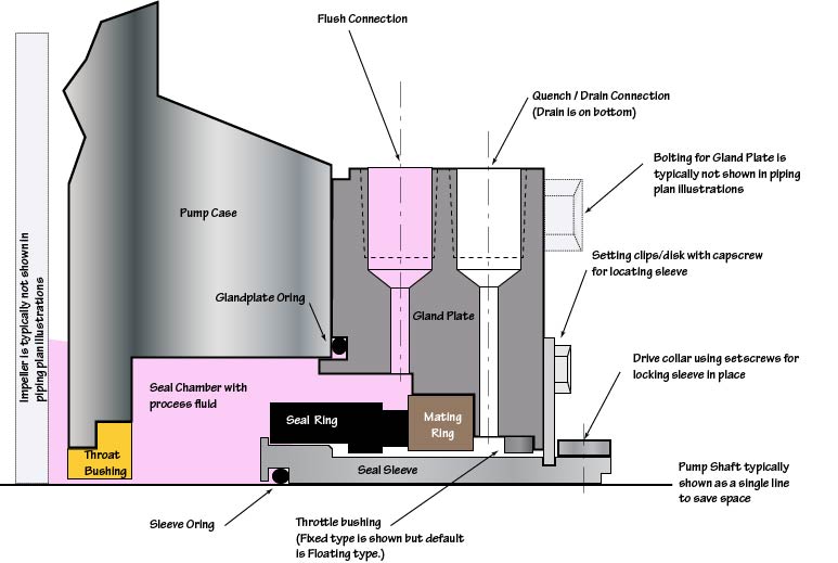
Piping plans are illustrated using a piping schematic as well as an illustration of the seal chamber and seal. The illustration below is an example of the seals along with a description of the various parts.