
Remember that the purpose of the mechanical seal is to prevent leakage but also that all seals leak. For the seals being examined, how would the leakage be described?
- No visible leak
- OK when running but leaks when shut down
- Slight drip
- Steady drip
- Spits and sputters
- Failed emissions test.
Keep the leakage description in mind as the faces are being examined.
The methodology used herein is to show examples of seal face problems and then discuss what happened and how to prevent it.
A check list is often used as an aid to recording observations. In this section, we’ll use a check list as a guide to failure analysis as well as organization of the section.
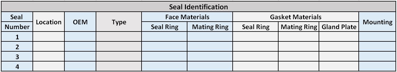
First, a simple method for identifying the seal being examined is needed. The pump may have only one seal or the pump might have, for example, tandem seals on each end of the pump. The table below will be used to identify the seal under examination.
Next is the checklist for recording observations of the seal ring or mating ring face. Remember that the seal ring is the flexible element – it moves axially to account for seal face wear and/or shaft movement. However, the seal ring can be rotating or stationary. Also, the seal ring can be the wide face part or the narrow face part.
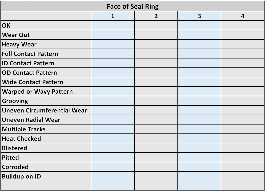
(For purposes of this article, the mating ring check list uses the same descriptions as the seal ring list.)
OK
Self explanatory, the face looks fine and contains no information worth recording. Little wear. Was this seal leaking? If the faces look good but leakage was noted then perhaps the secondary sealing elements are leaking.
Wear Out
Not many seals really wear out. Seals have an available wear length that is typically 1/16” to 3/16” long. When the available wear length has worn away, some other part or area begins to rub. For example, a thicker part of the seal ring might come into contact with the mating ring. For shrink fitted designs, the shell around the shrink fit might come into contact with the mating ring.
If the face is really worn out, be sure to look carefully for heat checking, presence of a flush and location of that flush. If there is more than one seal, consider the wear on the other seals. Was the shaft offset?
Heavy Wear
If the seal face appears to be badly worn, then perhaps
- service conditions are not as expected
- seal is not the right selection
- wrong materials
- no liquid around the seal
- loss of flush.
Clarification and additional information will probably be indicated by other observations. Look carefully for heat checking, presence of a flush and location of that flush. If there is more than one seal, consider the wear on the other seals. Was the shaft offset?
Full Contact Pattern
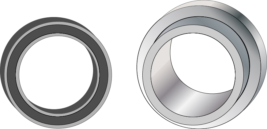
This is a desirable condition and indicates proper installation, operation, etc. The width of the narrow face should be measurable on the wider face. Was this seal leaking?
ID Contact Pattern
For many seal designs, an ID contact pattern is an indication of thermally induced distortion. This occurs when the seal faces are hot but the seal body is not. This is also called positive rotation (as in rigid body rotation of the shape.) The OD of the seal face may not even show contact. Is there a flush? Does the flush really flow all around the seal faces?
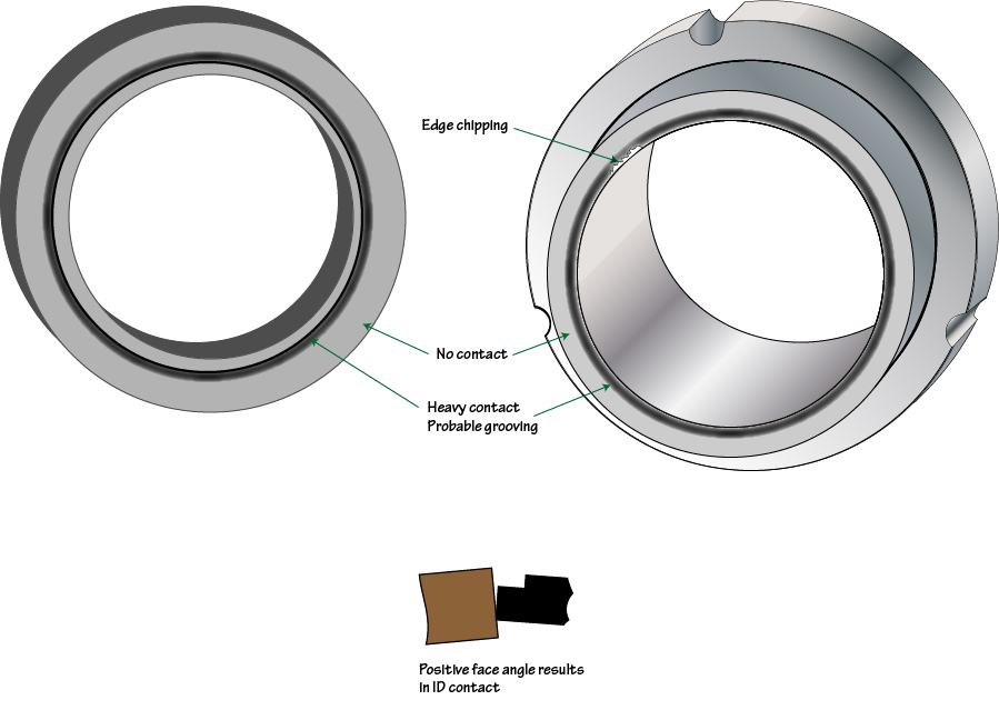
When using two hard faces, a seal may not have very much pressure induced distortion and thermal effects may be more prevalent. Note that, in particular, the coefficient of thermal expansion for bronze is very high such that bronze seal faces tend to contact towards the ID.
Be sure to note if the narrow face has chips on the ID. Also note if the wide face is grooved toward the ID.
OD Contact Pattern
For many seal designs, an OD contact pattern is an indication of pressure induced distortion. This is also called coning or negative rotation (as in rigid body rotation of the shape). The ID of the seal faces may not even indicate contact. What is the pressure in the seal chamber? Is the seal rated for this pressure? Note that the seal chamber pressure is not necessarily pump suction of discharge pressure. Is there a close clearance throat bushing that is being used to raise the seal chamber pressure? SealFAQs includes information about estimating seal chamber pressure.
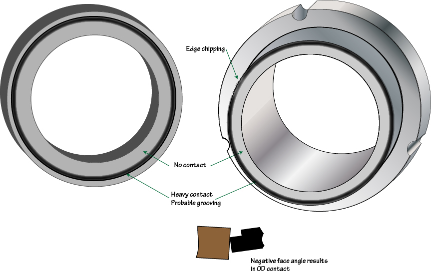
Be sure to note if the narrow face has chips on the OD and if the wide face is grooved towards the OD of the track.
Wide Contact Pattern
If the contact pattern on the wide face is wider than the width of the narrow face, then the narrow face component must be whirling instead of simply spinning. Check for a bent shaft or severe misalignment.
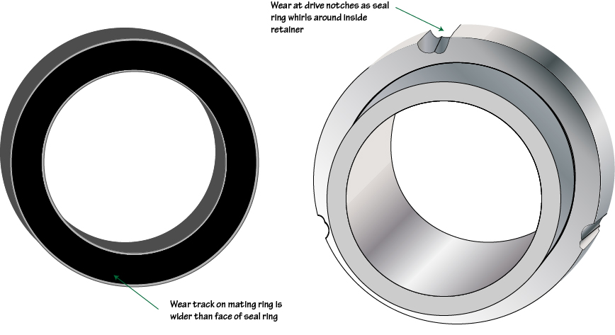
Is the bore of the mating ring or throttle bushing worn?
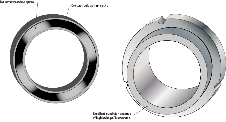
Wavy Pattern
If the seal face pattern is wavy (has high spots and low spots) then it was not flat during operation. Was the face actually lapped flat before installation? The face may have distorted during operation. Does the wavy pattern match the bolt pattern of the gland plate? Does the gland plate have full face contact to the seal chamber face? Is this a really large seal having only a single flush point?
Grooving
Many seal designs contact on the OD of the face when new and pressurized but before starting so it is not unusual to see a slight OD contact pattern; however, there should not be a deep groove at the OD of the wear pattern.
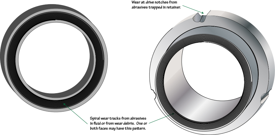
Heavy wear can also cause spiral grooving from the wear debris as it passes across the face. The narrow face can even wear deeply into the wide face even if the narrow face is made of carbon.
Abrasive particles getting between the seal faces can cause spiral grooving. Notice if the grooves extend all the way across the face. Not so long ago, this type of grooving was described as looking like a phonograph record but this description has become extremely dated!
Uneven Circumferential Wear
Something is badly misaligned such that the seal ring cannot compensate for it. For example, the gland plate could be cocked or the seal ring is stuck in the retainer and cannot flex. The stationary element may be cocked in the gland plate. Check any anti-rotation pins and make certain that they are not too long.
Uneven Radial Wear
When measured precisely, radial wear is almost always uneven because the thermal and pressure induced distortions do not exactly cancel out.
Multiple Tracks
Could be an indication of several different operating conditions. Does the pump sometimes, but not always, operate in series with another pump?
Heat Checked
Heat checks are fine radial cracks that are caused when a local hot spot is suddenly cooled. Heat checking is usually taken to mean that the flush was interrupted or never was present. Heat checking can also occur when the seal chamber is full of gas — the seal starts up dry, gets very hot and then is suddenly hit with liquid. Hard faces such as Stellite, alumina (ceramic) and tungsten carbide are subject to heat checking. Silicon carbide faces can show heat checking but this is somewhat rare. Carbon does not heat check but does “blister”.
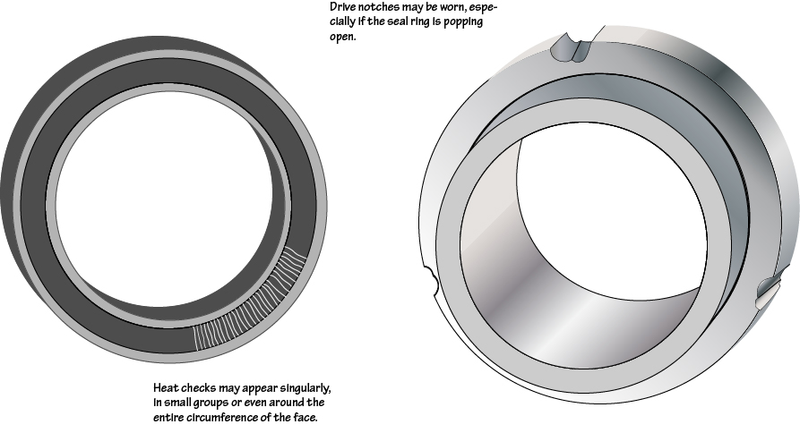
The heat check cracks will be only in the wear track. The heat check pattern may appear around the entire circumference of the wear track or only in localized spots. If the heat check pattern is on the stationary part then check the orientation of the pattern to the flush port.
In contrast to heat checks, if the hard face is uniformly very hot and then suddenly cooled, it may break into a number of approximately uniformly sized pieces. This is a gross thermal shock and is more likely to happen to alumina (ceramic) parts that it is to tungsten carbide or silicon carbide.
Blistered
The term “blistered” is often used to describe seal face damage but what does it mean?
Just like a blister on your hand, a blister on a carbon seal face is a bulge above the surface of the seal face. Blisters are produced while the seal is in service. Over a period of time, cracks develop in the blister, carbon pieces break away and a pit is left behind. The initial glossy, raised spot is called a Stage I blister; with cracks it becomes a Stage II blister. The pit is called a Stage III blister.
Blisters form only on carbon faces and then only in viscous oil service. Blistering gets worse with
- high viscosity
- synthetic polyalphaolefin oils
- frequent, rapid startups
- highly polished faces.
What causes blistering? The oldest explanation is that oil penetrates the pores, expands and pops out a carbon chip; however this is not correct. Instead, think of the oil film between the faces as a glue. When the seal begins to rotate, something has to break — either the carbon, the oil film or the hard face. This “glue” is stronger for more viscous oils and for very small seal face gaps. Each time the seal is started, the process repeats. The formation of the blister is ultimately a fatigue failure of the carbon graphite material.
A good rule of thumb is that blistering is possible if the oil is ISO 32 or higher and is very likely if the oil is ISO 68 or higher. In terms of viscosity, blistering is infrequent if the startup viscosity is less than 20 centipoise. Remember that the viscosity of oil changes drastically with temperature so startups on cold days are more likely to produce blisters.
How can blistering be prevented? Typically, the first approach is to use a metal filled carbon but all carbon grades are subject to blistering. Operationally, the end user could change to a low viscosity oil, warm up the oil, reduce the number of starts, etc. But often the user will not or cannot make these changes. For that reason, the classic fix for carbon blistering is: don’t use carbon — change to a hard face material such as silicon carbide, tungsten carbide, Ni-resist or bronze.
Pitted
As noted above, pitting may be Stage 3 blisters. When both seal faces use hard materials (for example, silicon carbide vs silicon carbide) and the liquid is very viscous (think in terms of tar), large pits may form. This type of pit is sometimes called “pull outs”.
Corroded
Modern seal face materials are usually very corrosion resistant; however, some of the older or less expensive materials may not be so resistant.
Leaching is a type of corrosion in which the binders in the material is removed by the fluid being sealed.
Buildup on ID
The product being sealed can solidify or decompose to leave a deposit on the seal face. Typically this will be at the ID of the narrow face. When sealing a hot hydrocarbon, this deposit is called “coke” and may even appear to be part of the face. Adding a steam quench can help with this problem but usually does not entirely prevent it.